
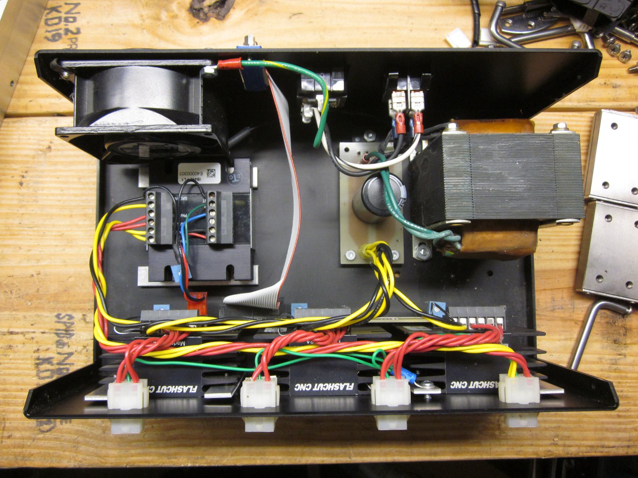
FlashCut CNC IB462 Driver Repair
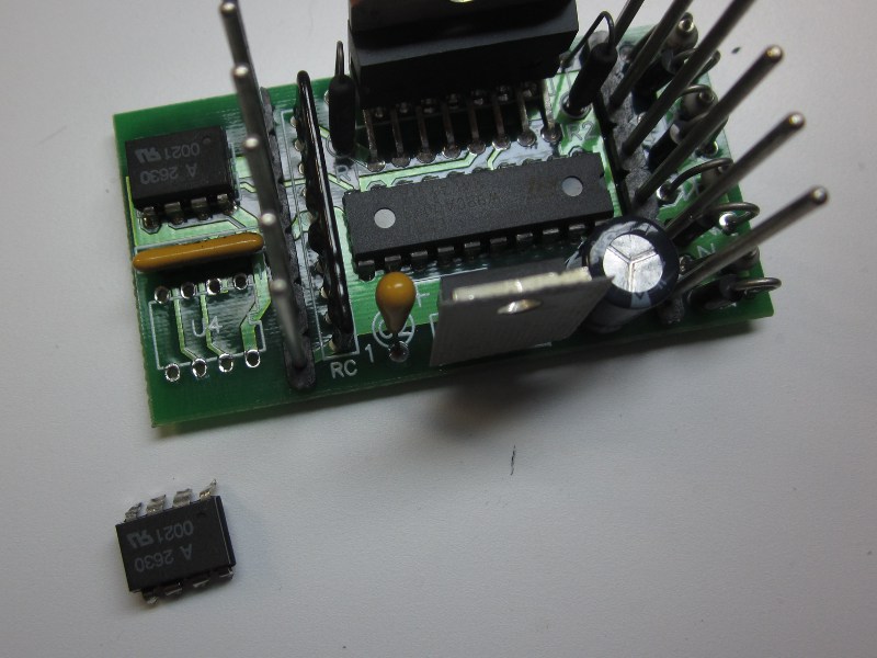
In the course of developing the BURPS stepper controller interface, I fried two of the IB462 driver modules in a FlashCut CNC Model 4020 drive system by inadvertently connecting the Step inputs to +5V without current regulation. With nothing to lose, I disassembled the drivers and discovered they used mostly common parts and were easily serviced. This process is detailed below to aid anyone in similar circumstances. The driver inputs can be quickly tested without disassembling the driver. Look for a 1.2-1.75V diode drop between each of the four signal inputs and Logic Ground. If the inputs read open or short, the optocoupler LED on that input has failed. (The Current Adjust input is not isolated; it is referenced to motor power ground.)

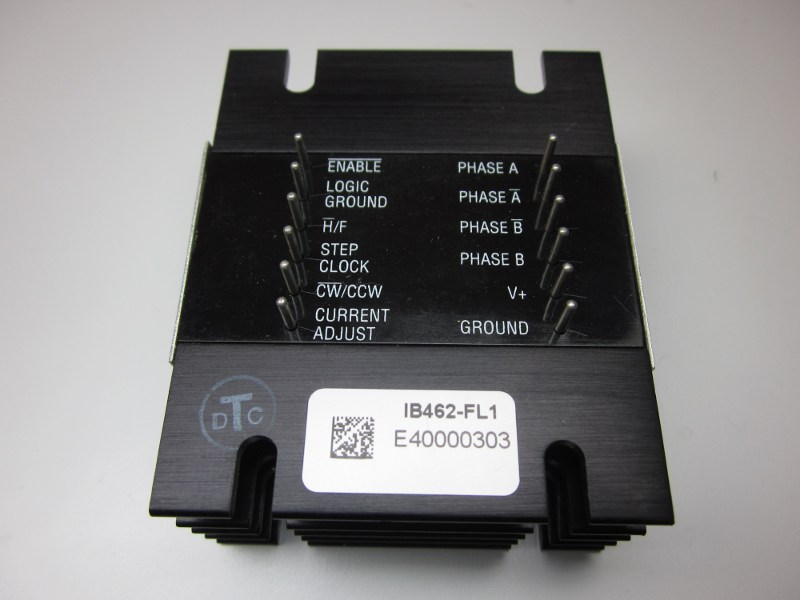 The FlashCut-branded end caps are self-adhesive aluminum plates, easily pried
off. The plastic lid is more difficult to remove. It's possible to pry up on
the plastic until it bows up and pops free. Compressing the heatsink fins in a
vise also works, but risks damaging the heatsink.
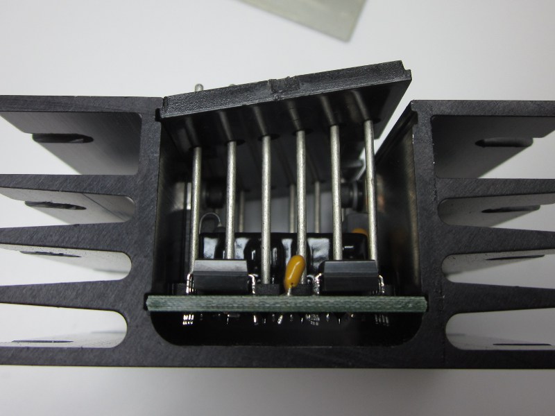
The power semiconductors are fixed to the heatsink with cap head screws which
take a 3/32" Allen key. Note that a plastic insulating washer is present on
the LM317HVT voltage regulator.
The FlashCut-branded end caps are self-adhesive aluminum plates, easily pried
off. The plastic lid is more difficult to remove. It's possible to pry up on
the plastic until it bows up and pops free. Compressing the heatsink fins in a
vise also works, but risks damaging the heatsink.
The power semiconductors are fixed to the heatsink with cap head screws which
take a 3/32" Allen key. Note that a plastic insulating washer is present on
the LM317HVT voltage regulator.
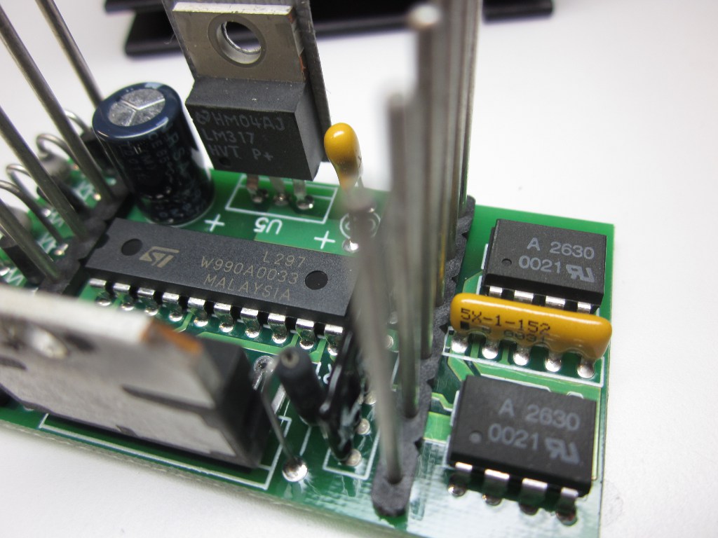
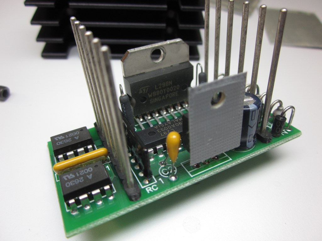
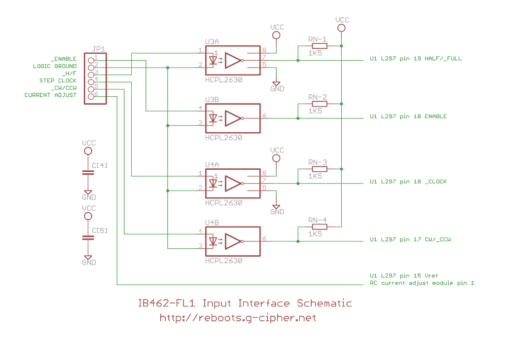
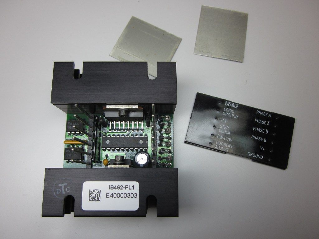 The topology of the driver is very typical. The Enable, Half/Full Step, Step
Clock, and CW/CCW inputs are isolated by Avago Technologies
HCPL-2630
dual optocouplers, connected common-cathode to Logic Ground and without series
resistors; a potentially fatal design flaw. The outputs are routed directly
to an STMicroelectronics
L297
stepper motor controller IC, operating an
L298N
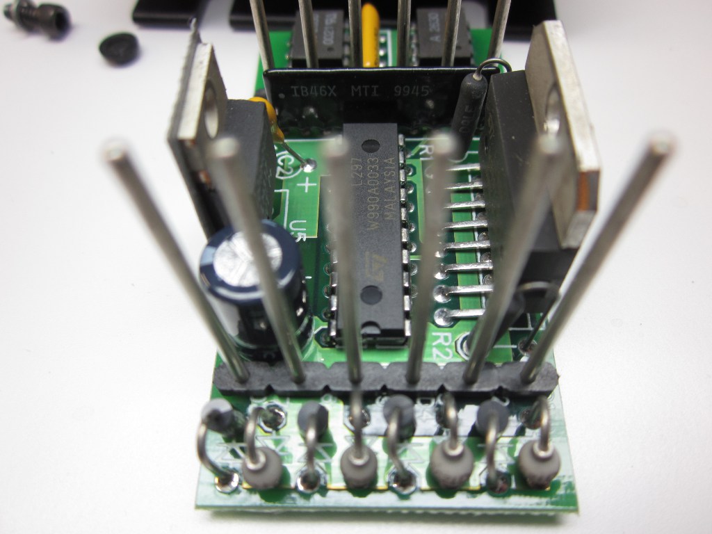
dual full bridge driver. Logic power is supplied by a LM317HVT adjustable
linear regulator. Current adjustment involves a potted circuit in SIP form,
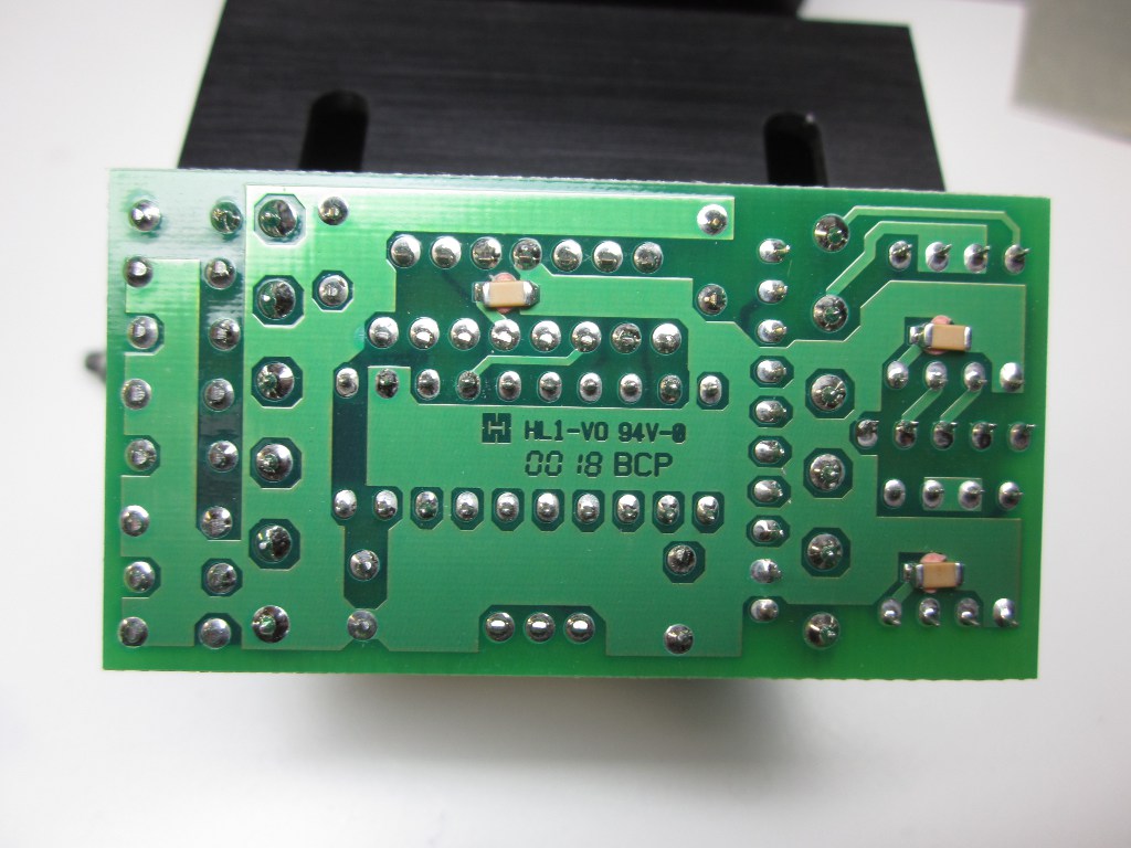
marked IB46X MTI 9945; possibly custom. The main PCB is easily traced,
although it has at least one buried layer.
The topology of the driver is very typical. The Enable, Half/Full Step, Step
Clock, and CW/CCW inputs are isolated by Avago Technologies
HCPL-2630
dual optocouplers, connected common-cathode to Logic Ground and without series
resistors; a potentially fatal design flaw. The outputs are routed directly
to an STMicroelectronics
L297
stepper motor controller IC, operating an
L298N
dual full bridge driver. Logic power is supplied by a LM317HVT adjustable
linear regulator. Current adjustment involves a potted circuit in SIP form,
marked IB46X MTI 9945; possibly custom. The main PCB is easily traced,
although it has at least one buried layer.
 Below is a schematic for the input portion of the driver, and a complete bill
of materials for the board:
Below is a schematic for the input portion of the driver, and a complete bill
of materials for the board:
| IB462-FL1_input_schematic.png | IB462-FL1 input schematic diagram in PNG format |
| IB462-FL1_bom.csv | IB462-FL1 bill of materials in CSV spreadsheet format |
 The drivers were reassembled and returned to fully functional service.
Contact: reboots at g-cipher.net
The drivers were reassembled and returned to fully functional service.
Contact: reboots at g-cipher.netXHTML and CSS compliant
:wq