
Clausing 8520 Milling Machine
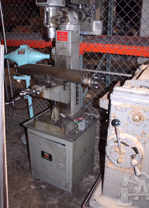
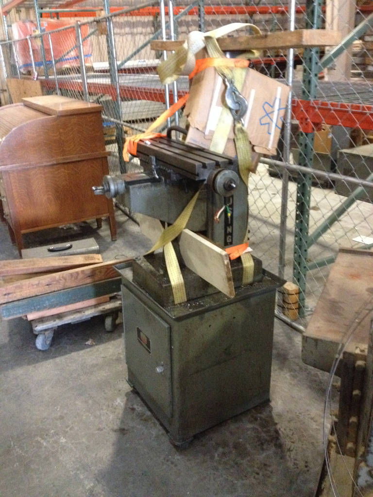
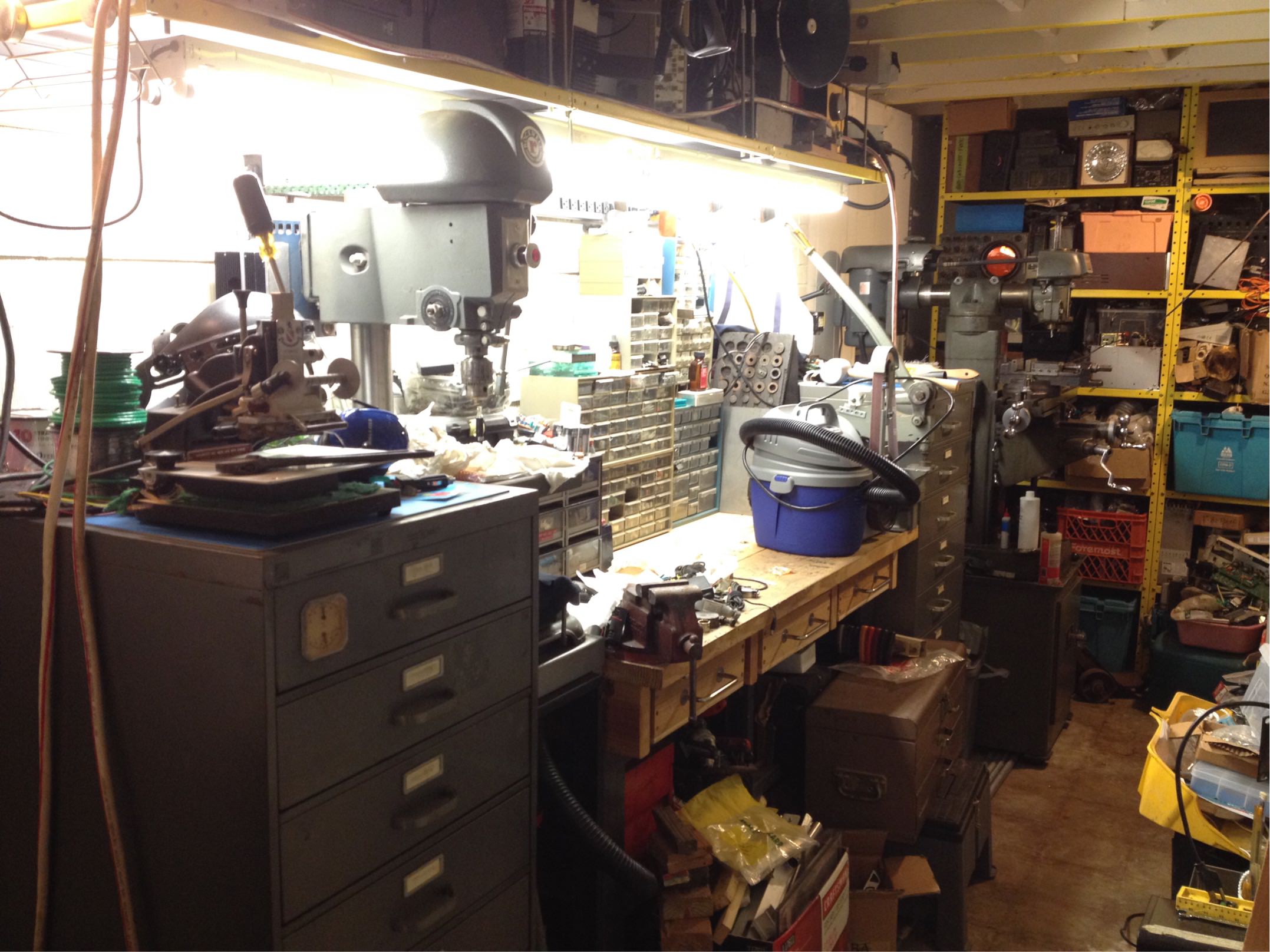
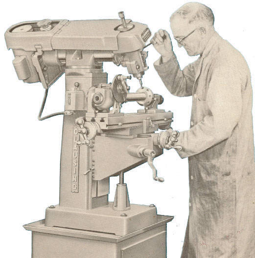 This is my Clausing 8520 milling machine. There are many like it, but this one is mine. I bought it at a university auction, condition unknown.
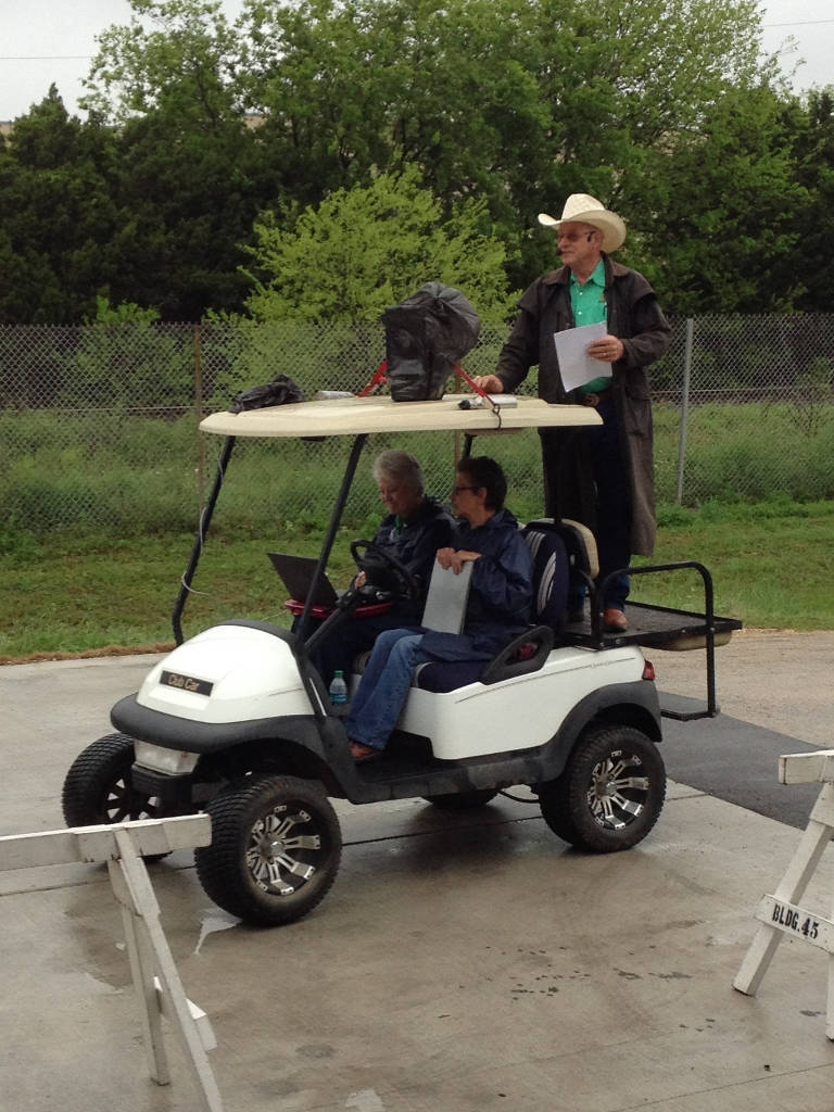
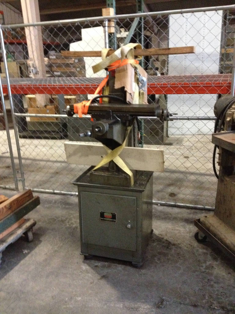
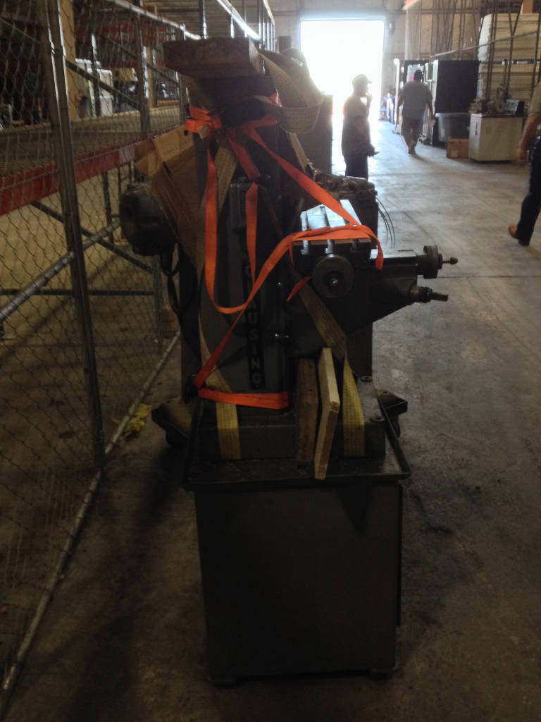
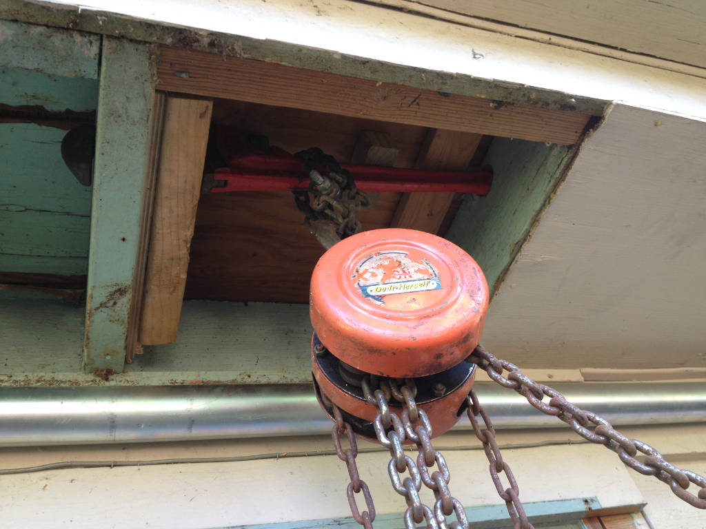
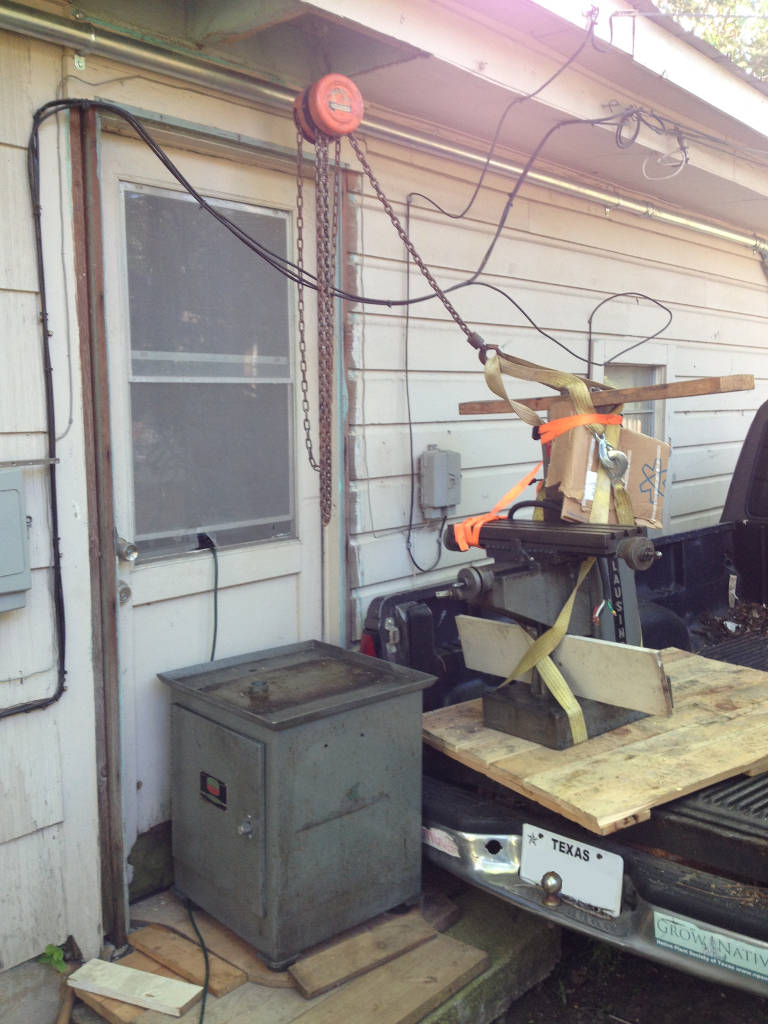
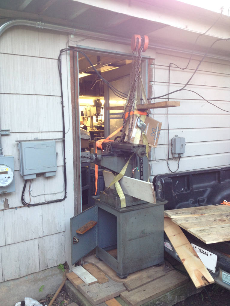
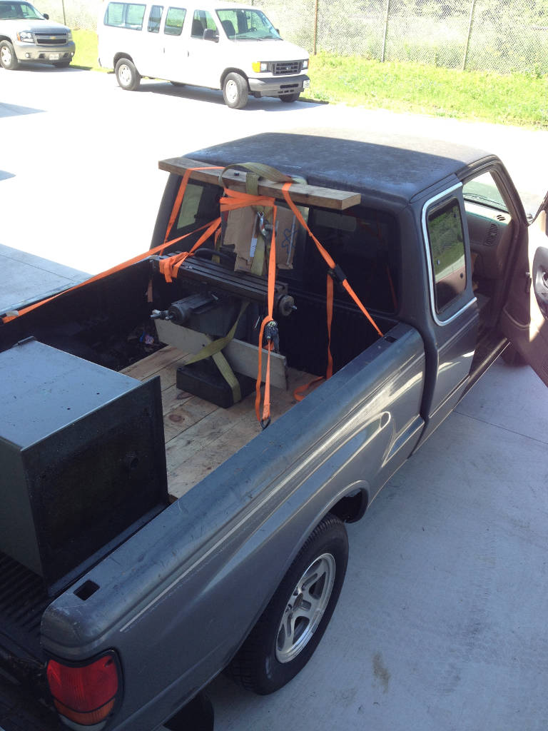 Here is an illustration of how not to lift a milling machine, even one so relatively petite.
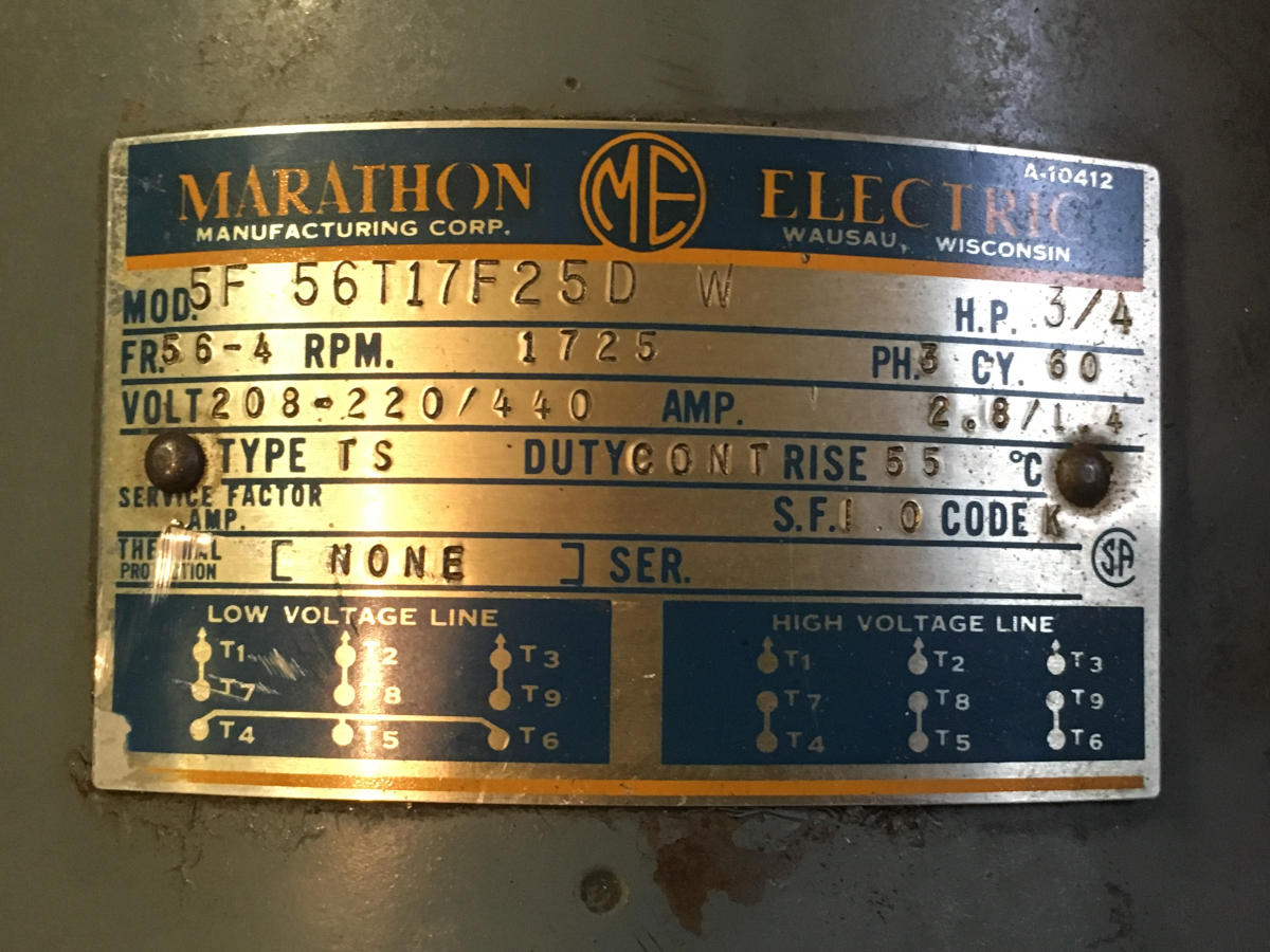
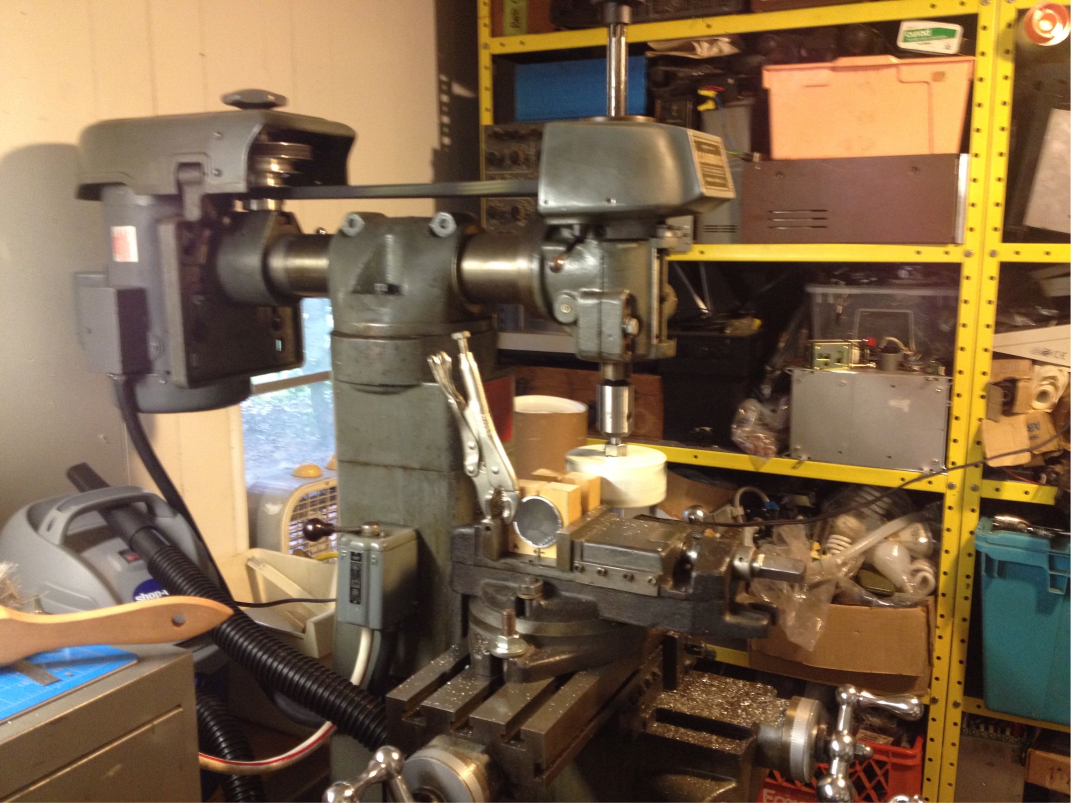
 The mill came with an unwired Marathon Electric 3/4HP 3-phase motor. Lacking
3-phase power, I mounted a 1.5HP Dayton 5K565AE motor I had on hand. Wiring
the motor to the Furnas R44 drum switch on the mill was a puzzle. I found
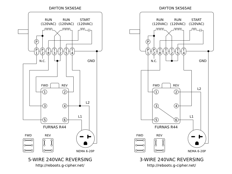
two methods for accomplishing what I wanted. The first and more common method
requires five conductors to the switch, and applies voltage to the motor even
in the off state. The second method I pieced together from demented ramblings
in some obscure forum. It requires only three conductors; the motor is
de-energized when shut off; and it works brilliantly. Both methods are
diagrammed below for your convenience.
The mill came with an unwired Marathon Electric 3/4HP 3-phase motor. Lacking
3-phase power, I mounted a 1.5HP Dayton 5K565AE motor I had on hand. Wiring
the motor to the Furnas R44 drum switch on the mill was a puzzle. I found
two methods for accomplishing what I wanted. The first and more common method
requires five conductors to the switch, and applies voltage to the motor even
in the off state. The second method I pieced together from demented ramblings
in some obscure forum. It requires only three conductors; the motor is
de-energized when shut off; and it works brilliantly. Both methods are
diagrammed below for your convenience.

 The mill fit right into my small workshop. With eBay-supplied 4" vise,
tooling, parallels, clamps, and various lubricants, it's ready for action.
Backlash is about .015" in X and Y, usable by an alert operator.
The sensitive quill feed gears are stripped, as is typical for this model.
The spindle has not been measured for runout, but it runs true by eye.
Satisfactory surface finishes are reliably obtained in steel and aluminum.
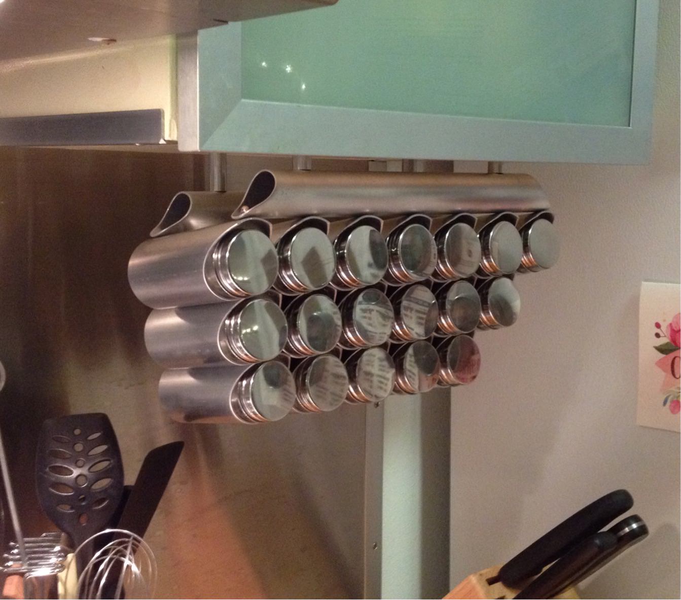
The first project was a nice spice rack, made from 2" aluminum tubing.
The mill fit right into my small workshop. With eBay-supplied 4" vise,
tooling, parallels, clamps, and various lubricants, it's ready for action.
Backlash is about .015" in X and Y, usable by an alert operator.
The sensitive quill feed gears are stripped, as is typical for this model.
The spindle has not been measured for runout, but it runs true by eye.
Satisfactory surface finishes are reliably obtained in steel and aluminum.
The first project was a nice spice rack, made from 2" aluminum tubing.
 My gratitude to Dale Wentz for his
excellent, highly informative technical reference on the 8520, from which
I stole the header image.
Substitute Inch/Metric Drawbar Assembly
My gratitude to Dale Wentz for his
excellent, highly informative technical reference on the 8520, from which
I stole the header image.
Substitute Inch/Metric Drawbar AssemblyFor most production years, the top of the 8520 spindle is threaded 3/4"-16 for a knurled cap nut which fits over the installed drawbar. The drawbar features a flange which is captured under the nut, but can spin freely. The square-drive drawbar head protrudes through a hole in the nut. When the drawbar is tightened, the flange is compressed against the top of the spindle and draws the collet upward. When loosened, the drawbar flange pushes against the knurled nut to pop the collet free. This system eliminates the need to hammer on the drawbar to loosen the collet, which can damage the spindle bearings and various other components. My mill came with the original drawbar, but the square drive had been rounded down and filed so many times that there was nothing left to grip. I had no access to a lathe or welding/brazing equipment, which ruled out the typical methods of fabricating a suitably flanged replacement. So I designed a workalike for the original Clausing captive-nut drawbar system, using only off-the-shelf parts from McMaster-Carr. A PDF drawing is available here: 8520_substitute_drawbar_assembly.pdf
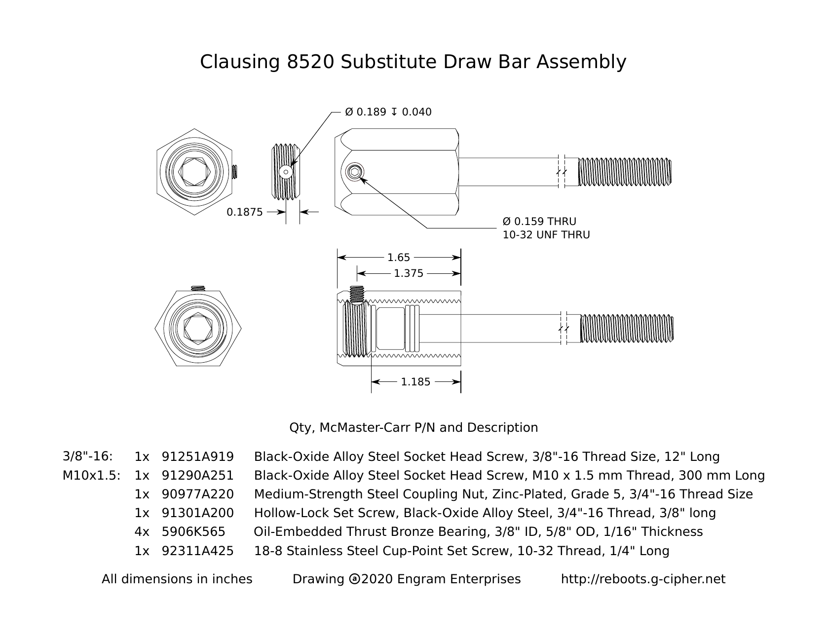 This assembly uses a commodity cap head screw instead of the flanged drawbar.
Since cap head screws are typically hardened, I added bronze thrust bearings
to prevent wear to the mating parts. In place of the knurled knob, I used a
3/4"-16 coupling nut with a mating hollow-lock set screw, installed and
pinned by a 10-32 set screw. The hollow-lock set screw has a 3/8" hex drive,
with sufficient through clearance for 5/16" and 8 mm hex keys to access
the cap head drawbar screw. During use, the head of the drawbar either
tightens against the top of the spindle or pushes against the hollow-lock
screw.
The McMaster-Carr part numbers are listed in the drawing, and duplicated
below with commentary.
This assembly uses a commodity cap head screw instead of the flanged drawbar.
Since cap head screws are typically hardened, I added bronze thrust bearings
to prevent wear to the mating parts. In place of the knurled knob, I used a
3/4"-16 coupling nut with a mating hollow-lock set screw, installed and
pinned by a 10-32 set screw. The hollow-lock set screw has a 3/8" hex drive,
with sufficient through clearance for 5/16" and 8 mm hex keys to access
the cap head drawbar screw. During use, the head of the drawbar either
tightens against the top of the spindle or pushes against the hollow-lock
screw.
The McMaster-Carr part numbers are listed in the drawing, and duplicated
below with commentary.
| Qty. | Part Number | Description | Notes |
| 91251A919 | Cap head screw, 3/8"-16 x 12" | Drawbar for 3/8" tooling | |
| 91290A251 | Cap head screw, M10-1.5 x 300 mm | Drawbar for M10 tooling | |
| 90977A220 | Steel coupling nut, 3/4"-16 | Engages the 3/4"-16 thread at the top of the spindle | |
| 91301A200 | Hollow-lock set screw, 3/4"-16 x 3/8" | 3/8" hex drive has through clearance for 5/16" and 8 mm drawbar hex keys | |
| 5906K565 | Bronze thrust bearing, 3/8" ID, 5/8" OD, 1/16" thick | Must be drilled to 10mm if M10 drawbar is used | |
| 92311A425 | Set screw, 10-32 x 1/4" | Keeps the hollow-lock screw fastened in the coupling nut | 5/16" and/or 8 mm hex keys | I already had these |
A participant in the Clausing Lathe and Mill mailing list requested dimensions for the 8520 table lock screws. My Y axis screw turned out to be badly worn, so I produced a drawing from the X axis screw by using a set of calipers. Dimensions may differ slightly from the original design; in particular, I had no way of measuring the diameter of the handle pivot roll pin, although I suspect it's standard 3/16". A PDF drawing is available here: 8520_table_lock_screw.pdf
 7" Rotary Table
Through a stroke of eBay luck, I found a 7" rotary table which appears identical to the Gulledge model originally sold with the Clausing mills. I can't find a make or model anywhere on it, so it might be a respectable clone. The center bore is a straight 5/8" hole, not tapered. I machined a bushing which fits in the bore, having a concentric 1/4-20" threaded hole with a reamed seat to accept a 1/4" shoulder screw. Workpieces are easily aligned with the table axis by drilling a 1/4" hole for a reference and pivot point. The bushing also has a pair of pegs made from cap head screws, which engage the t-slots to keep it from falling through the table and from rotating while tightening the shoulder screw. It's fastened from underneath the table by another 1/4" screw. The rotary table requires considerable cleverness and careful adjustment to articulate what would be elementary CNC toolpaths. But each successful result feels like a delightful accomplishment.


 Contact: reboots at g-cipher.net
XHTML and CSS compliant
:wq