Amy Time! Nixie Tube Clock
There are few original ideas: we revel in our small successes, secure on the
shoulders of generous giants. I hope the reader can use and improve upon the
information and techniques I present below; most didn't originate with me.
I've included a lot of excruciating detail for this reason. Design files
are linked throughout the text.
This project started life as a cute General Electric battery charger I bought at a hamfest. There was no model number, and it wasn't obvious what the charger powered. The extruded aluminum enclosure looked perfect for a clock.
![[GE battery charger front]](image/thumbs/ge1_th.jpg)
![[GE battery charger rear]](image/thumbs/ge2_th.jpg)
![[GE battery charger interior]](image/thumbs/ge3_th.jpg)
Many years ago my brother gave me a nixie tube clock kit from Peter Jensen's
TubeClock.com. The kit was easy to
assemble and has worked very well. I was impressed to see that instead of
rare and fragile 74141 nixie driver chips, or discrete transistor drivers,
Peter had used a
HV5622 high-voltage shift register manufactured by Supertex Inc. (now
Microchip).
I hadn't encountered the part before, but I saw that this approach conserved
PCB real estate; required a minimum of microcontroller I/O; and relied on a
relatively cheap current production part.
For my clock, I intended to use the same approach. I fabricated a couple of
breakout boards for the chip to cultivate familiarity with its operation
(and maybe reuse for future, less space-constrained nixie projects).
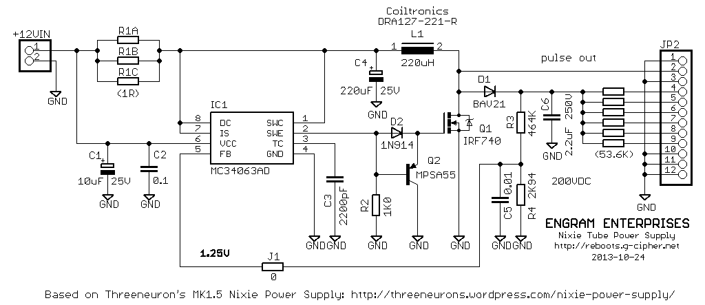
I wanted an efficient, reliable power supply based on the common and
inexpensive MC34063.
Threeneuron's design seemed well thought out, and he included part
numbers for the inductor and other critical components. I built a couple of
power supplies based on his circuit. They perform well, but the abrupt off
transition of the power FET results in dramatic high-frequency ringing. The
switching frequency is right at 1 kHz for a 200VDC output, and the ringing
sweeps across 458-543 kHz with a maximum amplitude of 102VAC (+86V/-16V).
It's obvious that a snubber network is needed, but I'm not sure how to
accurately measure the total capacitance at the FET output or calculate
the appropriate values. If you, the reader, can offer any tips, I'd love to
hear from you at the email address below.
PSU efficiency is very good, around 70-80%. It also "sings" audibly under
load, probably from electromechanical vibration in the power inductor at
the switching fundamental. I would be curious to see if a snubber network,
or better output decoupling, would help this problem. Since I was working
on a short timetable, I accepted the basic success and moved on.
I purchased two lots of 6 Russian surplus IN-12 tubes through eBay, one with
bakelite sockets. Shipping time was about three weeks. Quality
wasn't on par with the US-made tubes I've seen; there's a lot of dimensional
variance in the glass envelope and it's sometimes crooked relative to the
internal structure. If you're building a clock using IN-12s, I'd order extras
and select for best appearance.
It's important to carefully understand the power requirements of your tubes.
I started testing with a 20K anode resistor at 200V, which seemed reasonable
from the information on Threeneuron's site. After running a tube for several
hours, I could see evident cathode poisoning. The anode current was 3.5mA,
right at the top of the range for the IN-12. After some experimentation, I
settled on 53.4K (two 26.7K resistors in series, since that's what I had).
This supplied a much more conservative 1.3mA, which should promote longevity
of the tube and still yields decent brightness and visibility.
![[Breakout boards]](image/thumbs/breakouts_th.jpg)
![[Power supply prototype]](image/thumbs/nixieps_th.jpg)
With the prototype hardware ready, it was time to start writing code. The
HV5622 is easy to address in the typical manner of a shift register. For nixie
tube applications, Polarity (_POL, pin 27 of the PQFP variant) should be
permanently wired high. The HV5622 appears to power on with some or all of the
outputs enabled, possibly in a random state. It's wise to start with Blanking
(_BL, pin 33) low, shift in your desired initialization state, then bring
Blanking high to enable the display. (Polarity and Blanking have very similar
functions, which could probably be inverted. The TubeClock.com kit ties
Polarity high, so that's what I did.)
- Pull Clock high (CLK, pin 28).
- Set Data In (pin 32) high or low as needed.
- Pull Clock low. This shifts the bit into the register.
- Repeat until all 32 bits are shifted in.
- Pulse Latch Enable (_LE, pin 31) high then low. The data is
copied to the output latch.
Only 28 of the 32 outputs are needed for a 4-digit clock, 27 if you're
satisfied with 12-hour time: 1[-2], 0-9, 0-5, 0-9. It happened that I needed
to address the outputs in counterclockwise order; the shift routine is easily
modified for big- or little-endian shifting.
| time.asm |
AVR assembly language firmware for ATmega48, compiles with
gavrasm |
Below are pictures of the test setup. I used a four-channel Tektronix 2245A,
triggered off Latch Enable, to view continuous data sent to the shift
register and help debug my code. There's a triggering delay, so the signal
wraps around the display. The four peaks correspond to four active outputs,
one for a numeral in each tube.
![[HV5622 prototype]](image/thumbs/prototype1_th.jpg)
![[HV5622 scope view]](image/thumbs/prototype2_th.jpg)
With the code more-or-less squared away, I turned my attention to mechanical
design. Using digital calipers I measured the chassis, the tubes, and the
sockets, and made 2D vector drawings in
Inkscape. I scanned the original faceplate and imported the resulting
bitmap into Inkscape as well, scaling the object dimensions to match width
and height measurements of the real piece before converting the outline to
a vector object with opaque fill. Using these elements I was able to choose
the best placement for the tubes in the chassis and mock up a dummy
faceplate before doing any machining. I printed out paper templates and
affixed them to the metal parts with tape, then used a center punch to define
drill holes. This resulted in pretty good accuracy: the final clock assembly
matched my drawing in Inkscape to within about 1/32". The tube sockets just
barely fit in the steel chassis, and the faceplate needed to be positioned
just right to clear the enclosure--working from dimensioned templates was
tremendously helpful, and probably prevented a lot of rework and misery.
| IN-12.svg |
Dimensional drawing for IN-12 tube, socket, and front panel
cutout, in Scalable Vector Graphics format |
Pictured below are the original chassis with added framework for the tube
sockets, and the dummy faceplate. Looks encouraging!
![[Mockup disassembled]](image/thumbs/mockup1_th.jpg)
![[Mockup assembled]](image/thumbs/mockup2_th.jpg)
Painting the enclosure. The original navy blue enamel wasn't without its
charm, but it had undergone a lot of abuse and I wanted something more
festive. I used
Testors
Model Master spray paint. This was a terrifying experience for a novice.
The paint contains a lot of solvents which take a while to evaporate, so it
stays liquid for several minutes. Fresh from the can it splatters and sags;
over time surface tension draws the paint into a beautiful smooth finish that
conforms to the texture of the original enamel while concealing small
blemishes. I applied a cream coat over the enclosure components, let it cure
for 48 hours as recommended, and added red detailing using masking tape and
waxed paper. I had hoped the waxed paper would mask without sticking to the
cream,
but it was a terrible choice: the paint solvent attacked the "wax" coating
and red paint bled through in spots. The finish was very difficult to touch
up without leaving visible evidence.
After several days the paint had outgassed enough to be reasonably durable.
It's not as tough as powder coating, but it's not soft or pliable either.
![[Painting the enclosure]](image/thumbs/painting_th.jpg)
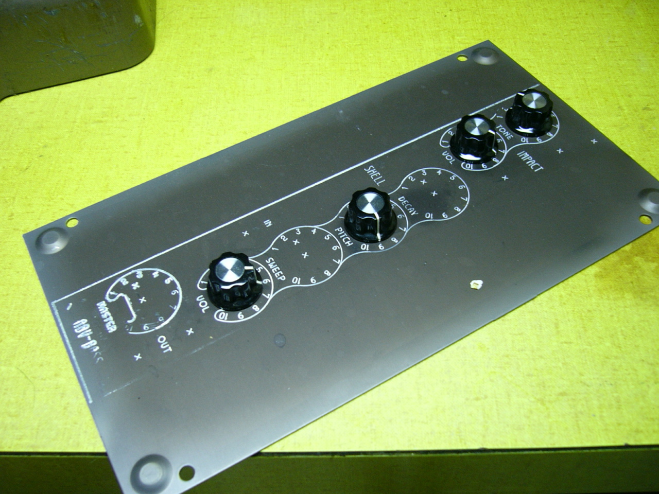
Time to get serious. I had idly sketched several ideas for the faceplate
legend in
CadSoft EAGLE, since
the grid feature made it easy to lay out the (mid-century) modern,
rectilinear design I had in mind. (Inkscape has a grid as well, but Eagle
was open at the time.) The doodle turned out well enough that I exported it
in PDF format, imported to Inkscape, and converted to paths. Eagle is
perfectly usable as a simple vector-drawing program; I've used it to make
several front panels, lettering and all.
(
Here's an
example, in the form of a moderately unsuccessful experiment to engrave
aluminum.)
I finalized the faceplate design in Inkscape and printed it in mirror-image
on the photo paper I use for PCB toner transfer. (Fry's Great Quality brand,
sadly long discontinued. Some day I'll exhaust my supply and have to find an
alternative.) I cut stainless steel sheet to outsize dimensions, brushed
it with 600-grit sandpaper to promote toner adhesion, and ironed the transfer
on high for several minutes. The results were very good, better than I
typically see with copper: only a few specks of toner, and one outside edge
of the design, failed to transfer.
On a whim, I painted over the transferred toner with a fine-tip paint pen.
This seemed unnecessary at the time, but turned out to be a prudent precaution.
I wanted a deep relief in the steel, and etched the workpiece in
room-temperature ferric chloride for around 40
minutes. The toner layer is slightly porous; this doesn't matter for thin PCB
copper cladding, but after the longer etch time discoloration and pitting
were visible wherever I hadn't touched up with paint. Using the paint pen, I
filled in the relief and let dry.
As I'd discovered previously, freehand abrasive brushing can offer a pleasing
finish; but it wasn't straight or consistent enough to reproduce the
industrial brushed look I wanted. I affixed 220-grit sandpaper to one 2x4
and the workpiece to another, using fiberglass carpet tape. Using smooth,
firm strokes I slid the 2x4s past each other, keeping them parallel against
the floor. Stopping or starting mid-stroke left unwanted marks, so finding
the right technique took some experimentation. Excess paint and much of the
pitting was removed; the resulting finish was excellent.
![[Faceplate toner transfer]](image/thumbs/fpetch1_th.jpg)
![[Etched faceplate]](image/thumbs/fpetch2_th.jpg)
![[Brushed faceplate]](image/thumbs/fpbrush_th.jpg)
I expected the workpiece to warp and burr slightly during the shaping process.
This would cause the sandpaper to ride high in some spots, resulting in an
uneven finish, so I elected to brush first and handle very carefully. Over the
course of shaping, the faceplate did indeed incur some small scratches and
burnish marks. I was able to remove these with a tab of sandpaper taped to
my finger, and light straight strokes over the trouble spots.
I had chosen a 1/4" radius cutout for the rounded corner of the IN-12,
adding pilot hole marks to the toner transfer design in Inkscape. I used a
step drill to drill these out to 1/2", and also drilled and deburred the
holes for the LED seconds display. Using a
Klein 76011B nibbling tool, I roughed out the center portion of the tube
cutouts. The Klein nibbler is a terrific tool, once you remove the hold-down
clamp that obscures the cut and mars the workpiece. Oil it when it squeaks,
and it will provide many years of service. Nibbling does distort the steel, so
I had to maintain at least 1/16" of distance from the edge of the
cutout. I fixed the faceplate in a vise with chunks of ABS plastic for
makeshift soft jaws, and painstakingly filed out the remaining material along
the guide lines etched into the workpiece.
In retrospect I wish I'd spent a little more time finishing out the cutouts,
maybe with fine-grit sandpaper wrapped around a dowel. I was afraid of
removing too much material, or slipping and marring the finish, which is why
I used hand tools exclusively. The result still looks fine from a normal
viewing distance, and pretty good close up. It's hard to know when to say when.
I clamped the increasingly delicate faceplate between two blocks of wood to
prevent warping or twisting, using waxed paper as a medium to prevent the
wood fiber from marring the finish under vibration and pressure. I used a
1" belt sander I bought at a hamfest, originally built for shaping golf
clubs, to grind away excess material around the faceplate outline, using
80-120 grit belts for rapid removal and a 400-grit belt for finishing. This
was an effective and controllable process; but friction increased as grit
was stripped from the belts, heating the workpiece and discoloring the edges.
I started quenching with water after each pass, and this was partially
effective.
The heat caused the waxed paper coating to melt and stick to the faceplate.
It had to be very carefully removed with acetone. Over the course of this
project, waxed paper is trending as a candidate for worst craft material of
all time.
![[Drilled faceplate]](image/thumbs/fpdrill_th.jpg)
![[Nibbled faceplate]](image/thumbs/fpnibble_th.jpg)
![[Shaped faceplate]](image/thumbs/fpshape_th.jpg)
The circuit design and PCB layout happened concurrently with chassis
fabrication. It wasn't until this point that I had a concrete idea of how
everything could be positioned in the cramped enclosure: power entry, time
set controls, display wiring, etc. The circuit comprised the following
elements:
- Maxim Integrated
DS32kHz 32.768kHz TCXO, which claims +/-1 minute/year
accuracy at typical room temperature and comes in a convenient SOIC
package.
- Atmel ATmega48 MCU, clocked from the internal RC oscillator and using the
DS32kHz as an external timer interrupt source.
- An array of 6 LEDs for a seconds display. I had several ideas for
various nifty time visualizations: PWM heartbeat, bargraph, Larson
Scanner, AM/PM status bits, etc. The timer code counts in half-seconds
to enable per-second blinking, which I didn't end up using. In the end
I fell back on the simple binary counter placeholder I wrote for
debugging the code, preset to start at 4 and roll over at 64 so all
six LEDs would indicate the last second of the minute. This doesn't
display the current second in a meaningful way, but it does indicate
the passage of time in a pleasant and engaging format.
- Buttons triggering external interrupts for setting the minute and
hour. I generally use external pull-ups because AVR internal pull-up
resistors aren't actually a guaranteed value, and in fact vary from
pin to pin. For the physical buttons, I used tactile switches with
stainless steel acorn nuts as button caps. The nuts were drilled out
to a
precise diameter and depth to fit over the switch actuators, and were
held captive by holes in the rear panel.
- A simple 5V linear power supply for the logic, and the high voltage
power supply design I'd prototyped. These are both powered from a 12VDC
SMPS wall wart, but the circuit as designed should be able to tolerate
input voltages from 7-24VDC and includes reverse voltage protection.
The cathode connections on the board are separated into discrete groups for
each digit, in an effort to prevent coupling from one digit to an adjacent
active ground for the next digit. This shouldn't be a problem at DC, but the
HVPS filtering isn't perfect and I was concerned that any AC component
might couple current and cause unwanted display artifacts. This was probably
completely unnecessary. It would be interesting to connect a set of tubes
in a sub-optimal way, e.g. over a few feet of fine-pitch ribbon cable, to
test whether this concern is warranted.
After the board was fabricated, I ended up doing some hackwork to add two
26.7K resistors in series for each anode. Additionally, the prototype PSUs
used 2.2uF 250V MLCC capacitors; I substituted aluminum electrolytic out
of concern for MLCC reliability. Since the tab of the IRF740 is at HV potential
and would contact the case for thermal dissipation, I used the isolated-tab
IRFI740 variant in the clock. A mica insulator might allow better thermal
transfer, but I wanted a high margin of safety. The tab of the mounted
IRFI740 was barely warm to the touch in operation.
The ISP header was originally intended to extend from the top layer of the PCB.
After fabricating the board, I decided to place it on the other side and add
an access plug in the rear panel. This allowed for uploading new firmware
without disassembling the clock, but the pinout is mirror-image: 2-1-4-3-6-5.
Alas! I used three 2-wire jumpers to swap the signals.
![[PCB schematic]](image/thumbs/time-schematic_th.jpg)
![[PCB front]](image/thumbs/timepcbfront_th.jpg)
![[PCB back]](image/thumbs/timepcbback_th.jpg)
With the PCB mounted in the chassis, I wired up the tube sockets using tinned
solid hookup wire and teflon sleeving. The wires were routed to avoid any
contact and possible coupling between digits (again, probably overkill). I
opted to buy sockets with the tubes and wire them point-to-point, reasoning
that this would be faster and simpler than building sockets from scratch on
a custom PCB. (See
Notes on DIY Nixie Tube Sockets.) In retrospect, the custom PCB route
might have been
cheaper while facilitating assembly considerably. Socketed mounting did offer
a little bit of flexibility over tube position. All the IN-12 sockets I have
are slightly rotated relative to the tube. Additionally, poor QC as noted
above means tube geometry varies noticeably. It was useful to be able to
tweak each tube position for best appearance before tightening the mounting
screws.
And, it's alive! Everything worked great from first light, except that I'd
wired both numerals 1 and 2 in the first tube to give the option of 24-hour
time, and my code somehow transposed them. A small software fix, plus a few
tweaks for button debouncing and the LED display, and the software was ready
for a few days of timekeeping and burn-in.
The clock draws between 80-140mA at 12V, depending on how many LEDs are lit.
![[Nixie socket wiring]](image/thumbs/wiring_th.jpg)
![[Clock programming]](image/thumbs/programming_th.jpg)
I did some deep and lengthy head-scratching over how to fasten the faceplates.
The original battery charger used panel-mount components to hold the front and
rear panels to the chassis. I didn't have anything like that here, and I didn't
want to use visible fasteners, but the panels needed to be secure. I ended
up fabricating brackets and epoxying them to the panels
with
JB Weld. I don't
have a lot of confidence in JB Weld for small scale applications, but it
worked great here.
![[Components ready for assembly]](image/thumbs/components_th.jpg)
![[Chassis with faceplates]](image/thumbs/chassis_th.jpg)
Happy Birthday, Amy!
![[Clock face]](image/thumbs/timeface_th.jpg)
![[Clock left view]](image/thumbs/timeleft_th.jpg)
![[Clock right view]](image/thumbs/timeright_th.jpg)
![[Clock rear view]](image/thumbs/timerear_th.jpg)
![[Clock detail]](image/thumbs/timedetail_th.jpg)
![[Clock with lamp]](image/thumbs/timelamp_th.jpg)
![[Clock with desk]](image/thumbs/timedesk_th.jpg)
![[Clock angle view]](image/thumbs/timeangle_th.jpg)
It's been a few weeks (update: five years), and the clock keeps time as
well as the other devices I have to compare.
If you have any questions or comments, or if you've derived any use from the
information presented herein, I'd be delighted to hear from you.
Contact: reboots at g-cipher.net
XHTML and CSS compliant
:wq

![[GE battery charger front]](image/ge1.jpg)
![[GE battery charger rear]](image/ge2.jpg)
![[GE battery charger interior]](image/ge3.jpg) Many years ago my brother gave me a nixie tube clock kit from Peter Jensen's
TubeClock.com. The kit was easy to
assemble and has worked very well. I was impressed to see that instead of
rare and fragile 74141 nixie driver chips, or discrete transistor drivers,
Peter had used a
HV5622 high-voltage shift register manufactured by Supertex Inc. (now
Microchip).
I hadn't encountered the part before, but I saw that this approach conserved
PCB real estate; required a minimum of microcontroller I/O; and relied on a
relatively cheap current production part.
For my clock, I intended to use the same approach. I fabricated a couple of
breakout boards for the chip to cultivate familiarity with its operation
(and maybe reuse for future, less space-constrained nixie projects).
I wanted an efficient, reliable power supply based on the common and
inexpensive MC34063.
Threeneuron's design seemed well thought out, and he included part
numbers for the inductor and other critical components. I built a couple of
power supplies based on his circuit. They perform well, but the abrupt off
transition of the power FET results in dramatic high-frequency ringing. The
switching frequency is right at 1 kHz for a 200VDC output, and the ringing
sweeps across 458-543 kHz with a maximum amplitude of 102VAC (+86V/-16V).
It's obvious that a snubber network is needed, but I'm not sure how to
accurately measure the total capacitance at the FET output or calculate
the appropriate values. If you, the reader, can offer any tips, I'd love to
hear from you at the email address below.
PSU efficiency is very good, around 70-80%. It also "sings" audibly under
load, probably from electromechanical vibration in the power inductor at
the switching fundamental. I would be curious to see if a snubber network,
or better output decoupling, would help this problem. Since I was working
on a short timetable, I accepted the basic success and moved on.
Many years ago my brother gave me a nixie tube clock kit from Peter Jensen's
TubeClock.com. The kit was easy to
assemble and has worked very well. I was impressed to see that instead of
rare and fragile 74141 nixie driver chips, or discrete transistor drivers,
Peter had used a
HV5622 high-voltage shift register manufactured by Supertex Inc. (now
Microchip).
I hadn't encountered the part before, but I saw that this approach conserved
PCB real estate; required a minimum of microcontroller I/O; and relied on a
relatively cheap current production part.
For my clock, I intended to use the same approach. I fabricated a couple of
breakout boards for the chip to cultivate familiarity with its operation
(and maybe reuse for future, less space-constrained nixie projects).
I wanted an efficient, reliable power supply based on the common and
inexpensive MC34063.
Threeneuron's design seemed well thought out, and he included part
numbers for the inductor and other critical components. I built a couple of
power supplies based on his circuit. They perform well, but the abrupt off
transition of the power FET results in dramatic high-frequency ringing. The
switching frequency is right at 1 kHz for a 200VDC output, and the ringing
sweeps across 458-543 kHz with a maximum amplitude of 102VAC (+86V/-16V).
It's obvious that a snubber network is needed, but I'm not sure how to
accurately measure the total capacitance at the FET output or calculate
the appropriate values. If you, the reader, can offer any tips, I'd love to
hear from you at the email address below.
PSU efficiency is very good, around 70-80%. It also "sings" audibly under
load, probably from electromechanical vibration in the power inductor at
the switching fundamental. I would be curious to see if a snubber network,
or better output decoupling, would help this problem. Since I was working
on a short timetable, I accepted the basic success and moved on.
![[Breakout boards]](image/breakouts.jpg)
![[Power supply prototype]](image/nixieps.jpg) With the prototype hardware ready, it was time to start writing code. The
HV5622 is easy to address in the typical manner of a shift register. For nixie
tube applications, Polarity (_POL, pin 27 of the PQFP variant) should be
permanently wired high. The HV5622 appears to power on with some or all of the
outputs enabled, possibly in a random state. It's wise to start with Blanking
(_BL, pin 33) low, shift in your desired initialization state, then bring
Blanking high to enable the display. (Polarity and Blanking have very similar
functions, which could probably be inverted. The TubeClock.com kit ties
Polarity high, so that's what I did.)
With the prototype hardware ready, it was time to start writing code. The
HV5622 is easy to address in the typical manner of a shift register. For nixie
tube applications, Polarity (_POL, pin 27 of the PQFP variant) should be
permanently wired high. The HV5622 appears to power on with some or all of the
outputs enabled, possibly in a random state. It's wise to start with Blanking
(_BL, pin 33) low, shift in your desired initialization state, then bring
Blanking high to enable the display. (Polarity and Blanking have very similar
functions, which could probably be inverted. The TubeClock.com kit ties
Polarity high, so that's what I did.)
![[HV5622 prototype]](image/prototype1.jpg)
![[HV5622 scope view]](image/prototype2.jpg) With the code more-or-less squared away, I turned my attention to mechanical
design. Using digital calipers I measured the chassis, the tubes, and the
sockets, and made 2D vector drawings in
Inkscape. I scanned the original faceplate and imported the resulting
bitmap into Inkscape as well, scaling the object dimensions to match width
and height measurements of the real piece before converting the outline to
a vector object with opaque fill. Using these elements I was able to choose
the best placement for the tubes in the chassis and mock up a dummy
faceplate before doing any machining. I printed out paper templates and
affixed them to the metal parts with tape, then used a center punch to define
drill holes. This resulted in pretty good accuracy: the final clock assembly
matched my drawing in Inkscape to within about 1/32". The tube sockets just
barely fit in the steel chassis, and the faceplate needed to be positioned
just right to clear the enclosure--working from dimensioned templates was
tremendously helpful, and probably prevented a lot of rework and misery.
With the code more-or-less squared away, I turned my attention to mechanical
design. Using digital calipers I measured the chassis, the tubes, and the
sockets, and made 2D vector drawings in
Inkscape. I scanned the original faceplate and imported the resulting
bitmap into Inkscape as well, scaling the object dimensions to match width
and height measurements of the real piece before converting the outline to
a vector object with opaque fill. Using these elements I was able to choose
the best placement for the tubes in the chassis and mock up a dummy
faceplate before doing any machining. I printed out paper templates and
affixed them to the metal parts with tape, then used a center punch to define
drill holes. This resulted in pretty good accuracy: the final clock assembly
matched my drawing in Inkscape to within about 1/32". The tube sockets just
barely fit in the steel chassis, and the faceplate needed to be positioned
just right to clear the enclosure--working from dimensioned templates was
tremendously helpful, and probably prevented a lot of rework and misery.
![[Mockup disassembled]](image/mockup1.jpg)
![[Mockup assembled]](image/mockup2.jpg) Painting the enclosure. The original navy blue enamel wasn't without its
charm, but it had undergone a lot of abuse and I wanted something more
festive. I used
Testors
Model Master spray paint. This was a terrifying experience for a novice.
The paint contains a lot of solvents which take a while to evaporate, so it
stays liquid for several minutes. Fresh from the can it splatters and sags;
over time surface tension draws the paint into a beautiful smooth finish that
conforms to the texture of the original enamel while concealing small
blemishes. I applied a cream coat over the enclosure components, let it cure
for 48 hours as recommended, and added red detailing using masking tape and
waxed paper. I had hoped the waxed paper would mask without sticking to the
cream,
but it was a terrible choice: the paint solvent attacked the "wax" coating
and red paint bled through in spots. The finish was very difficult to touch
up without leaving visible evidence.
After several days the paint had outgassed enough to be reasonably durable.
It's not as tough as powder coating, but it's not soft or pliable either.
Painting the enclosure. The original navy blue enamel wasn't without its
charm, but it had undergone a lot of abuse and I wanted something more
festive. I used
Testors
Model Master spray paint. This was a terrifying experience for a novice.
The paint contains a lot of solvents which take a while to evaporate, so it
stays liquid for several minutes. Fresh from the can it splatters and sags;
over time surface tension draws the paint into a beautiful smooth finish that
conforms to the texture of the original enamel while concealing small
blemishes. I applied a cream coat over the enclosure components, let it cure
for 48 hours as recommended, and added red detailing using masking tape and
waxed paper. I had hoped the waxed paper would mask without sticking to the
cream,
but it was a terrible choice: the paint solvent attacked the "wax" coating
and red paint bled through in spots. The finish was very difficult to touch
up without leaving visible evidence.
After several days the paint had outgassed enough to be reasonably durable.
It's not as tough as powder coating, but it's not soft or pliable either.
![[Painting the enclosure]](image/painting.jpg) Time to get serious. I had idly sketched several ideas for the faceplate
legend in CadSoft EAGLE, since
the grid feature made it easy to lay out the (mid-century) modern,
rectilinear design I had in mind. (Inkscape has a grid as well, but Eagle
was open at the time.) The doodle turned out well enough that I exported it
in PDF format, imported to Inkscape, and converted to paths. Eagle is
perfectly usable as a simple vector-drawing program; I've used it to make
several front panels, lettering and all.
(Here's an
example, in the form of a moderately unsuccessful experiment to engrave
aluminum.)
I finalized the faceplate design in Inkscape and printed it in mirror-image
on the photo paper I use for PCB toner transfer. (Fry's Great Quality brand,
sadly long discontinued. Some day I'll exhaust my supply and have to find an
alternative.) I cut stainless steel sheet to outsize dimensions, brushed
it with 600-grit sandpaper to promote toner adhesion, and ironed the transfer
on high for several minutes. The results were very good, better than I
typically see with copper: only a few specks of toner, and one outside edge
of the design, failed to transfer.
On a whim, I painted over the transferred toner with a fine-tip paint pen.
This seemed unnecessary at the time, but turned out to be a prudent precaution.
I wanted a deep relief in the steel, and etched the workpiece in
room-temperature ferric chloride for around 40
minutes. The toner layer is slightly porous; this doesn't matter for thin PCB
copper cladding, but after the longer etch time discoloration and pitting
were visible wherever I hadn't touched up with paint. Using the paint pen, I
filled in the relief and let dry.
As I'd discovered previously, freehand abrasive brushing can offer a pleasing
finish; but it wasn't straight or consistent enough to reproduce the
industrial brushed look I wanted. I affixed 220-grit sandpaper to one 2x4
and the workpiece to another, using fiberglass carpet tape. Using smooth,
firm strokes I slid the 2x4s past each other, keeping them parallel against
the floor. Stopping or starting mid-stroke left unwanted marks, so finding
the right technique took some experimentation. Excess paint and much of the
pitting was removed; the resulting finish was excellent.
Time to get serious. I had idly sketched several ideas for the faceplate
legend in CadSoft EAGLE, since
the grid feature made it easy to lay out the (mid-century) modern,
rectilinear design I had in mind. (Inkscape has a grid as well, but Eagle
was open at the time.) The doodle turned out well enough that I exported it
in PDF format, imported to Inkscape, and converted to paths. Eagle is
perfectly usable as a simple vector-drawing program; I've used it to make
several front panels, lettering and all.
(Here's an
example, in the form of a moderately unsuccessful experiment to engrave
aluminum.)
I finalized the faceplate design in Inkscape and printed it in mirror-image
on the photo paper I use for PCB toner transfer. (Fry's Great Quality brand,
sadly long discontinued. Some day I'll exhaust my supply and have to find an
alternative.) I cut stainless steel sheet to outsize dimensions, brushed
it with 600-grit sandpaper to promote toner adhesion, and ironed the transfer
on high for several minutes. The results were very good, better than I
typically see with copper: only a few specks of toner, and one outside edge
of the design, failed to transfer.
On a whim, I painted over the transferred toner with a fine-tip paint pen.
This seemed unnecessary at the time, but turned out to be a prudent precaution.
I wanted a deep relief in the steel, and etched the workpiece in
room-temperature ferric chloride for around 40
minutes. The toner layer is slightly porous; this doesn't matter for thin PCB
copper cladding, but after the longer etch time discoloration and pitting
were visible wherever I hadn't touched up with paint. Using the paint pen, I
filled in the relief and let dry.
As I'd discovered previously, freehand abrasive brushing can offer a pleasing
finish; but it wasn't straight or consistent enough to reproduce the
industrial brushed look I wanted. I affixed 220-grit sandpaper to one 2x4
and the workpiece to another, using fiberglass carpet tape. Using smooth,
firm strokes I slid the 2x4s past each other, keeping them parallel against
the floor. Stopping or starting mid-stroke left unwanted marks, so finding
the right technique took some experimentation. Excess paint and much of the
pitting was removed; the resulting finish was excellent.
![[Faceplate toner transfer]](image/fpetch1.jpg)
![[Etched faceplate]](image/fpetch2.jpg)
![[Brushed faceplate]](image/fpbrush.jpg) I expected the workpiece to warp and burr slightly during the shaping process.
This would cause the sandpaper to ride high in some spots, resulting in an
uneven finish, so I elected to brush first and handle very carefully. Over the
course of shaping, the faceplate did indeed incur some small scratches and
burnish marks. I was able to remove these with a tab of sandpaper taped to
my finger, and light straight strokes over the trouble spots.
I had chosen a 1/4" radius cutout for the rounded corner of the IN-12,
adding pilot hole marks to the toner transfer design in Inkscape. I used a
step drill to drill these out to 1/2", and also drilled and deburred the
holes for the LED seconds display. Using a
Klein 76011B nibbling tool, I roughed out the center portion of the tube
cutouts. The Klein nibbler is a terrific tool, once you remove the hold-down
clamp that obscures the cut and mars the workpiece. Oil it when it squeaks,
and it will provide many years of service. Nibbling does distort the steel, so
I had to maintain at least 1/16" of distance from the edge of the
cutout. I fixed the faceplate in a vise with chunks of ABS plastic for
makeshift soft jaws, and painstakingly filed out the remaining material along
the guide lines etched into the workpiece.
In retrospect I wish I'd spent a little more time finishing out the cutouts,
maybe with fine-grit sandpaper wrapped around a dowel. I was afraid of
removing too much material, or slipping and marring the finish, which is why
I used hand tools exclusively. The result still looks fine from a normal
viewing distance, and pretty good close up. It's hard to know when to say when.
I clamped the increasingly delicate faceplate between two blocks of wood to
prevent warping or twisting, using waxed paper as a medium to prevent the
wood fiber from marring the finish under vibration and pressure. I used a
1" belt sander I bought at a hamfest, originally built for shaping golf
clubs, to grind away excess material around the faceplate outline, using
80-120 grit belts for rapid removal and a 400-grit belt for finishing. This
was an effective and controllable process; but friction increased as grit
was stripped from the belts, heating the workpiece and discoloring the edges.
I started quenching with water after each pass, and this was partially
effective.
The heat caused the waxed paper coating to melt and stick to the faceplate.
It had to be very carefully removed with acetone. Over the course of this
project, waxed paper is trending as a candidate for worst craft material of
all time.
I expected the workpiece to warp and burr slightly during the shaping process.
This would cause the sandpaper to ride high in some spots, resulting in an
uneven finish, so I elected to brush first and handle very carefully. Over the
course of shaping, the faceplate did indeed incur some small scratches and
burnish marks. I was able to remove these with a tab of sandpaper taped to
my finger, and light straight strokes over the trouble spots.
I had chosen a 1/4" radius cutout for the rounded corner of the IN-12,
adding pilot hole marks to the toner transfer design in Inkscape. I used a
step drill to drill these out to 1/2", and also drilled and deburred the
holes for the LED seconds display. Using a
Klein 76011B nibbling tool, I roughed out the center portion of the tube
cutouts. The Klein nibbler is a terrific tool, once you remove the hold-down
clamp that obscures the cut and mars the workpiece. Oil it when it squeaks,
and it will provide many years of service. Nibbling does distort the steel, so
I had to maintain at least 1/16" of distance from the edge of the
cutout. I fixed the faceplate in a vise with chunks of ABS plastic for
makeshift soft jaws, and painstakingly filed out the remaining material along
the guide lines etched into the workpiece.
In retrospect I wish I'd spent a little more time finishing out the cutouts,
maybe with fine-grit sandpaper wrapped around a dowel. I was afraid of
removing too much material, or slipping and marring the finish, which is why
I used hand tools exclusively. The result still looks fine from a normal
viewing distance, and pretty good close up. It's hard to know when to say when.
I clamped the increasingly delicate faceplate between two blocks of wood to
prevent warping or twisting, using waxed paper as a medium to prevent the
wood fiber from marring the finish under vibration and pressure. I used a
1" belt sander I bought at a hamfest, originally built for shaping golf
clubs, to grind away excess material around the faceplate outline, using
80-120 grit belts for rapid removal and a 400-grit belt for finishing. This
was an effective and controllable process; but friction increased as grit
was stripped from the belts, heating the workpiece and discoloring the edges.
I started quenching with water after each pass, and this was partially
effective.
The heat caused the waxed paper coating to melt and stick to the faceplate.
It had to be very carefully removed with acetone. Over the course of this
project, waxed paper is trending as a candidate for worst craft material of
all time.
![[Drilled faceplate]](image/fpdrill.jpg)
![[Nibbled faceplate]](image/fpnibble.jpg)
![[Shaped faceplate]](image/fpshape.jpg) The circuit design and PCB layout happened concurrently with chassis
fabrication. It wasn't until this point that I had a concrete idea of how
everything could be positioned in the cramped enclosure: power entry, time
set controls, display wiring, etc. The circuit comprised the following
elements:
The circuit design and PCB layout happened concurrently with chassis
fabrication. It wasn't until this point that I had a concrete idea of how
everything could be positioned in the cramped enclosure: power entry, time
set controls, display wiring, etc. The circuit comprised the following
elements:
![[PCB schematic]](time-schematic.png)
![[PCB front]](image/timepcbfront.jpg)
![[PCB back]](image/timepcbback.jpg)
![[Nixie socket wiring]](image/wiring.jpg)
![[Clock programming]](image/programming.jpg) I did some deep and lengthy head-scratching over how to fasten the faceplates.
The original battery charger used panel-mount components to hold the front and
rear panels to the chassis. I didn't have anything like that here, and I didn't
want to use visible fasteners, but the panels needed to be secure. I ended
up fabricating brackets and epoxying them to the panels
with JB Weld. I don't
have a lot of confidence in JB Weld for small scale applications, but it
worked great here.
I did some deep and lengthy head-scratching over how to fasten the faceplates.
The original battery charger used panel-mount components to hold the front and
rear panels to the chassis. I didn't have anything like that here, and I didn't
want to use visible fasteners, but the panels needed to be secure. I ended
up fabricating brackets and epoxying them to the panels
with JB Weld. I don't
have a lot of confidence in JB Weld for small scale applications, but it
worked great here.
![[Components ready for assembly]](image/components.jpg)
![[Chassis with faceplates]](image/chassis.jpg) Happy Birthday, Amy!
Happy Birthday, Amy!
![[Clock face]](image/timeface.jpg)
![[Clock left view]](image/timeleft.jpg)
![[Clock right view]](image/timeright.jpg)
![[Clock rear view]](image/timerear.jpg)
![[Clock detail]](image/timedetail.jpg)
![[Clock with lamp]](image/timelamp.jpg)
![[Clock with desk]](image/timedesk.jpg)
![[Clock angle view]](image/timeangle.jpg) It's been a few weeks (update: five years), and the clock keeps time as
well as the other devices I have to compare.
If you have any questions or comments, or if you've derived any use from the
information presented herein, I'd be delighted to hear from you.
Contact: reboots at g-cipher.net
It's been a few weeks (update: five years), and the clock keeps time as
well as the other devices I have to compare.
If you have any questions or comments, or if you've derived any use from the
information presented herein, I'd be delighted to hear from you.
Contact: reboots at g-cipher.net