
The Rabbot
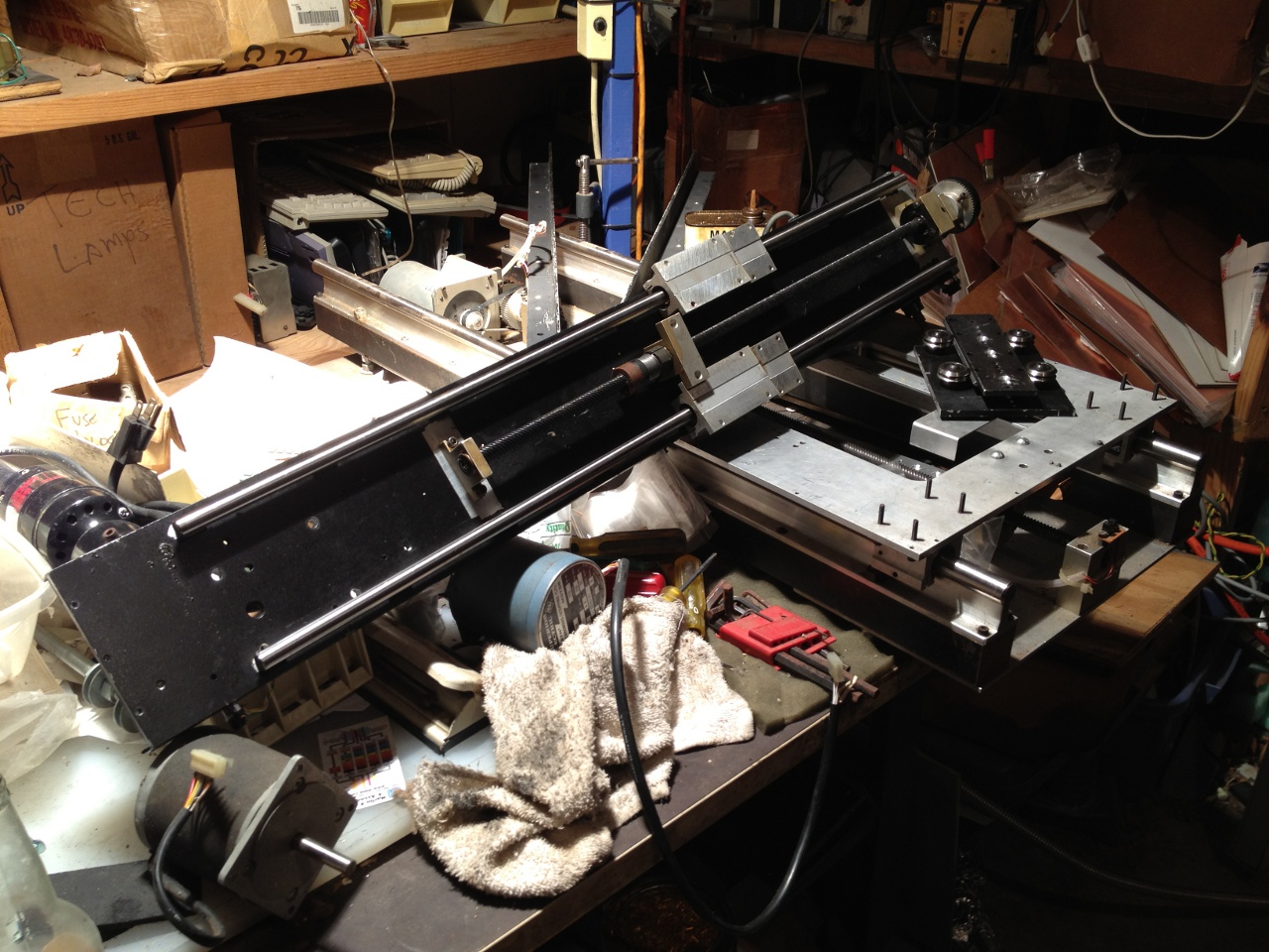
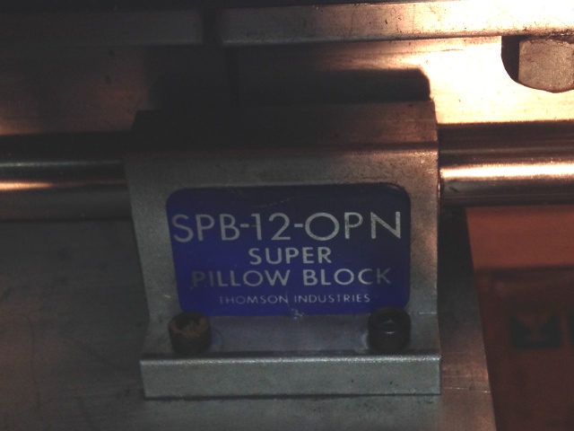
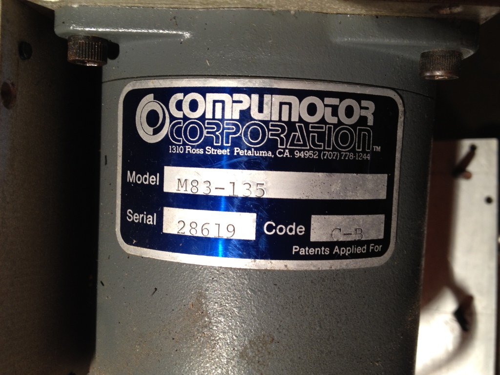
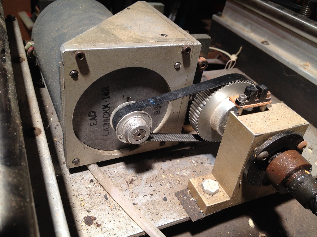
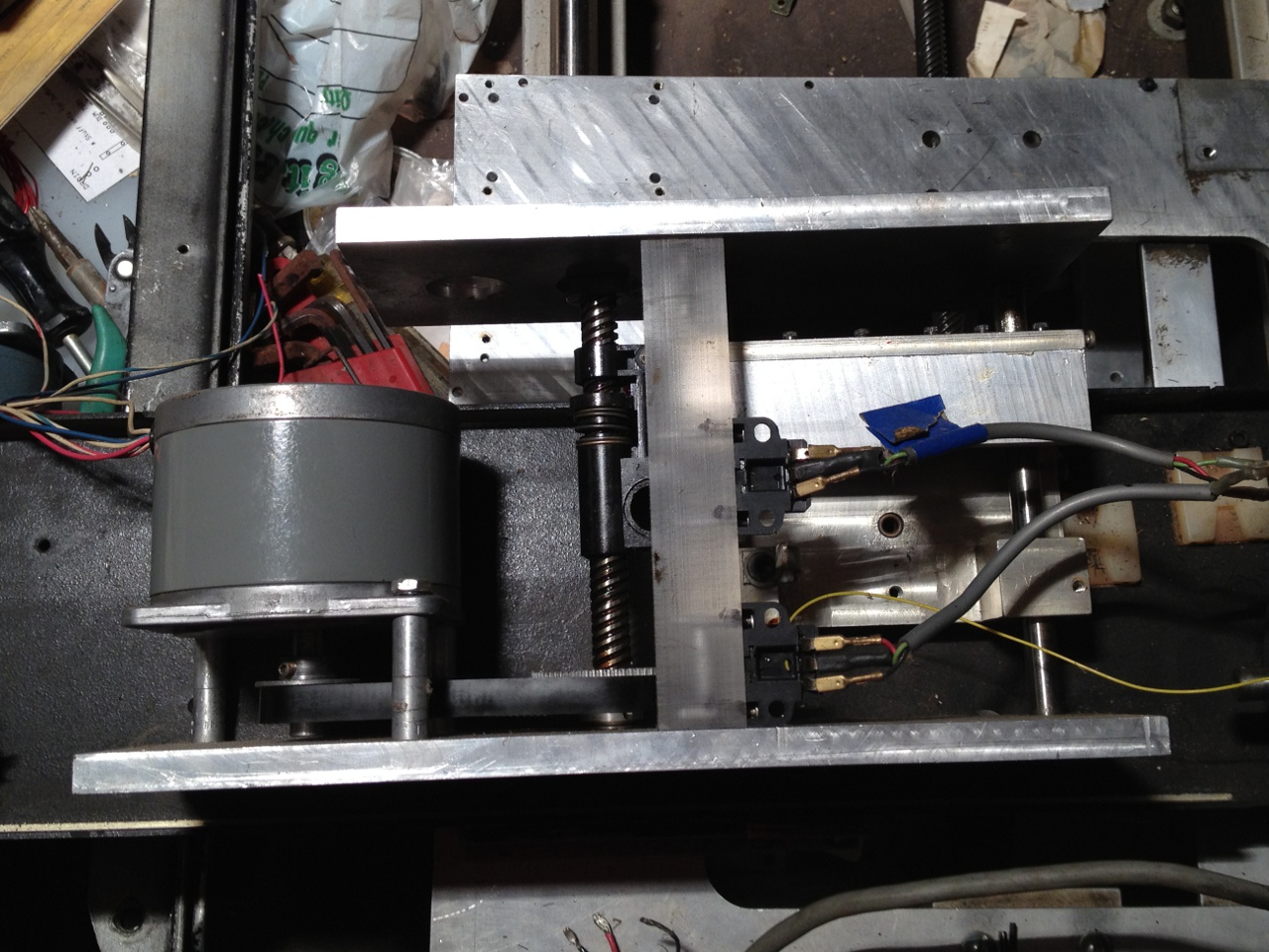
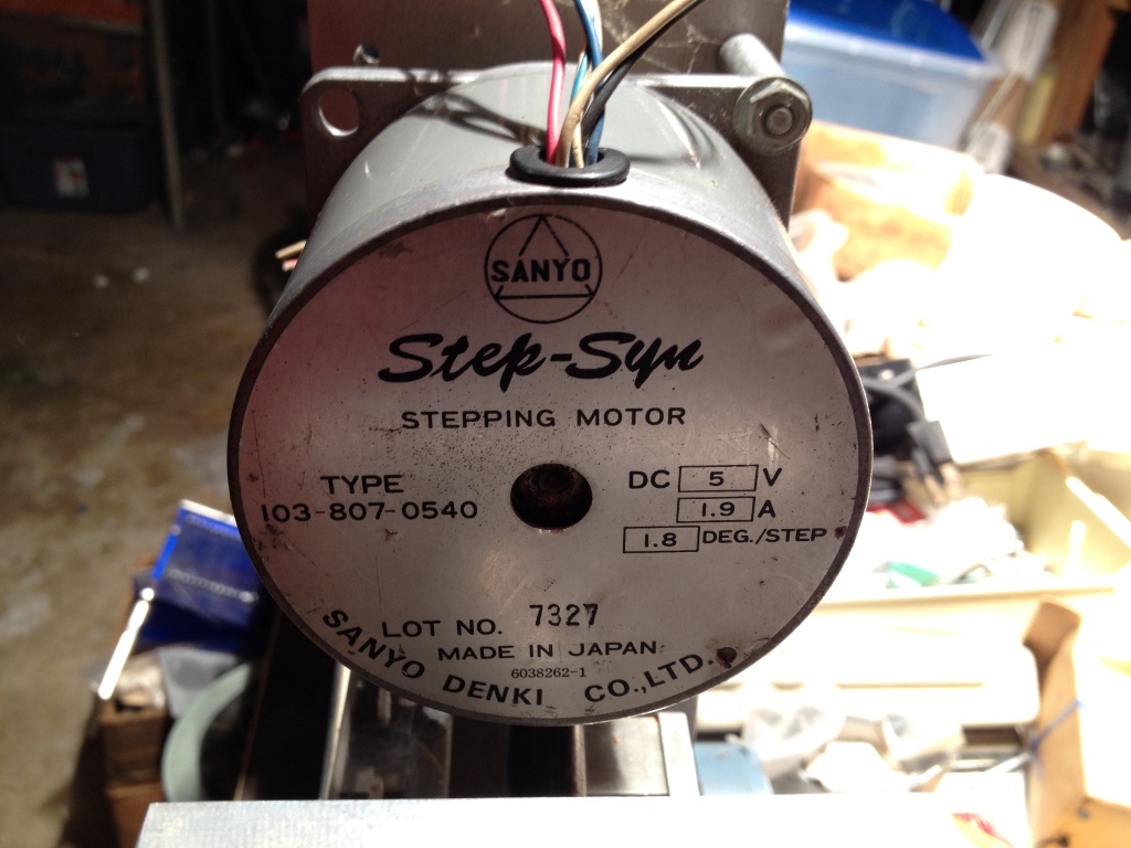
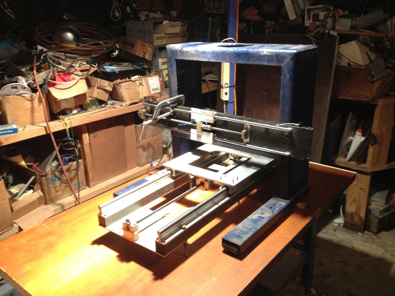
An adventure in making a quick-and-dirty CNC router, with minimal financial outlay as a primary design constraint. The Rabbot project started as a random collection of parts from a homebrew CNC router a friend acquired through a business liquidation sale. The original design was very poorly conceived: the Y axis gantry was an aluminum box cantilevered over the workspace, with the Y carriage bolted to the X axis carriage. Since all the structural components were 1/4" aluminum plate, rigidity was very poor. The Z axis rode on v-bearings which had no method of adjustment, and were binding badly; the actuator was a plastic-framed lead screw assembly apparently reused from an 8" floppy drive. Despite the poor construction, the constituent parts were of good quality. The X and Y axes are self-contained motion table modules; it's possible these were salvaged whole from some long-forgotten industrial application. The linear slides are Thomson Industries Super Pillow Block bearings and supported round rails. The motion components are 1/2" 8-start 8 TPI screws and hard plastic 2-piece anti-backlash nuts of unknown make. X and Y are powered by two Compumotor Corporation M83-135 stepper motors (NEMA-34, 400 oz-in, 1.8A, 1.8 deg/step). Z is powered by a Sanyo Step-Syn type 103-807-0540 stepper motor (5V, 1.9A, 1.8 deg/step). The X and Y screws are driven with synchronous timing belts. The pulleys used are 3 MM pitch HTD type, originally fitted with noticeably improper belts (apparently a stretched MXL pitch). The correct belts were purchased through Amazon.com:
| X Axis Belt | Ametric 2823M9 | HTD Rubber Timing Belt, 3mm Pitch, 282mm Long, 9mm Wide, 94 Teeth |
| Y Axis Belt | Ametric 2913M9 | HTD Rubber Timing Belt, 3mm Pitch, 291mm Long, 9mm Wide, 97 Teeth |

 The Controller
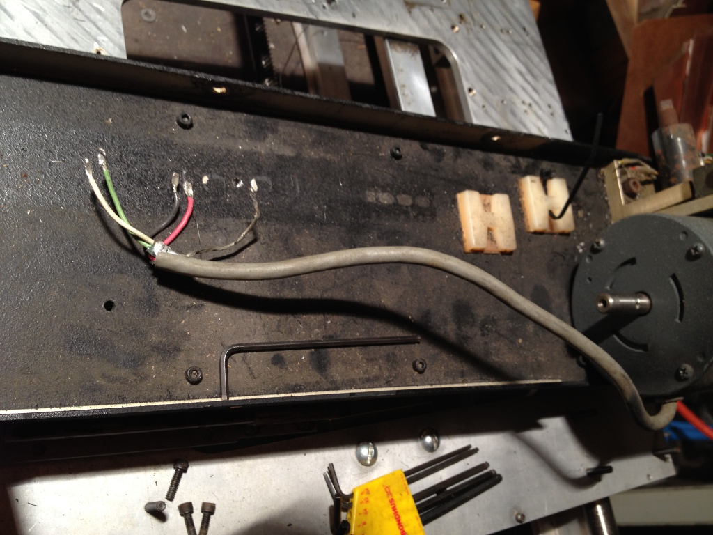
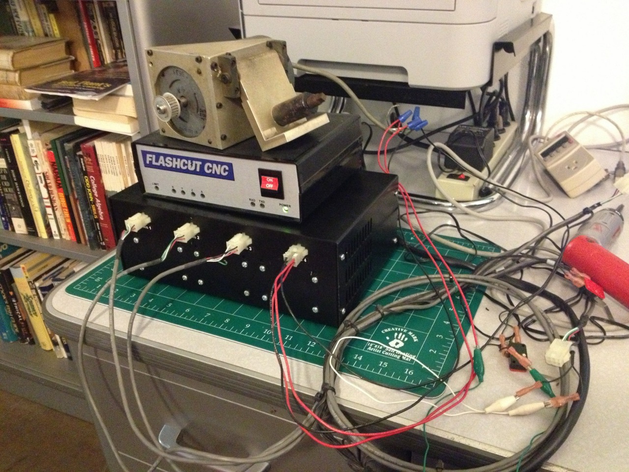
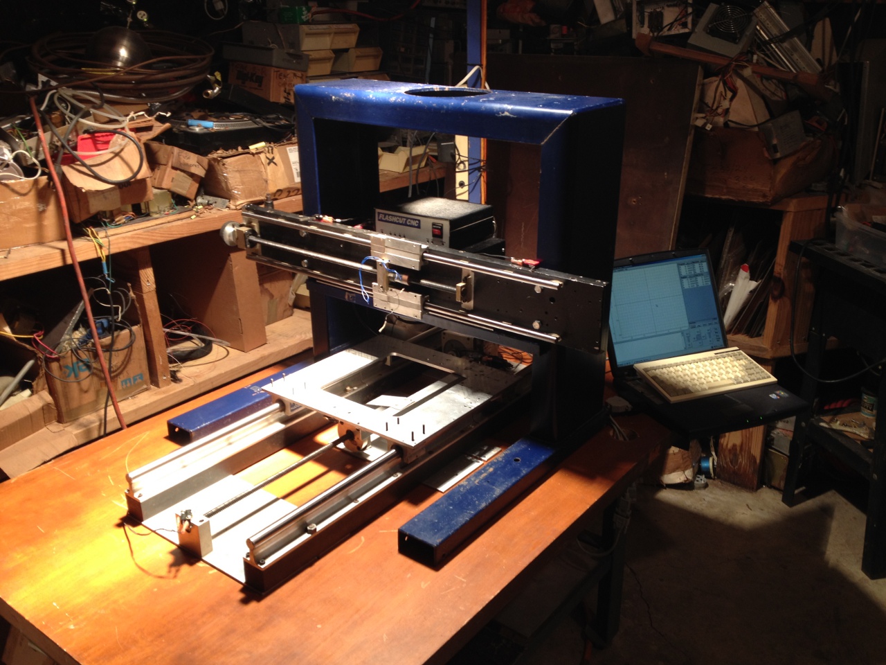
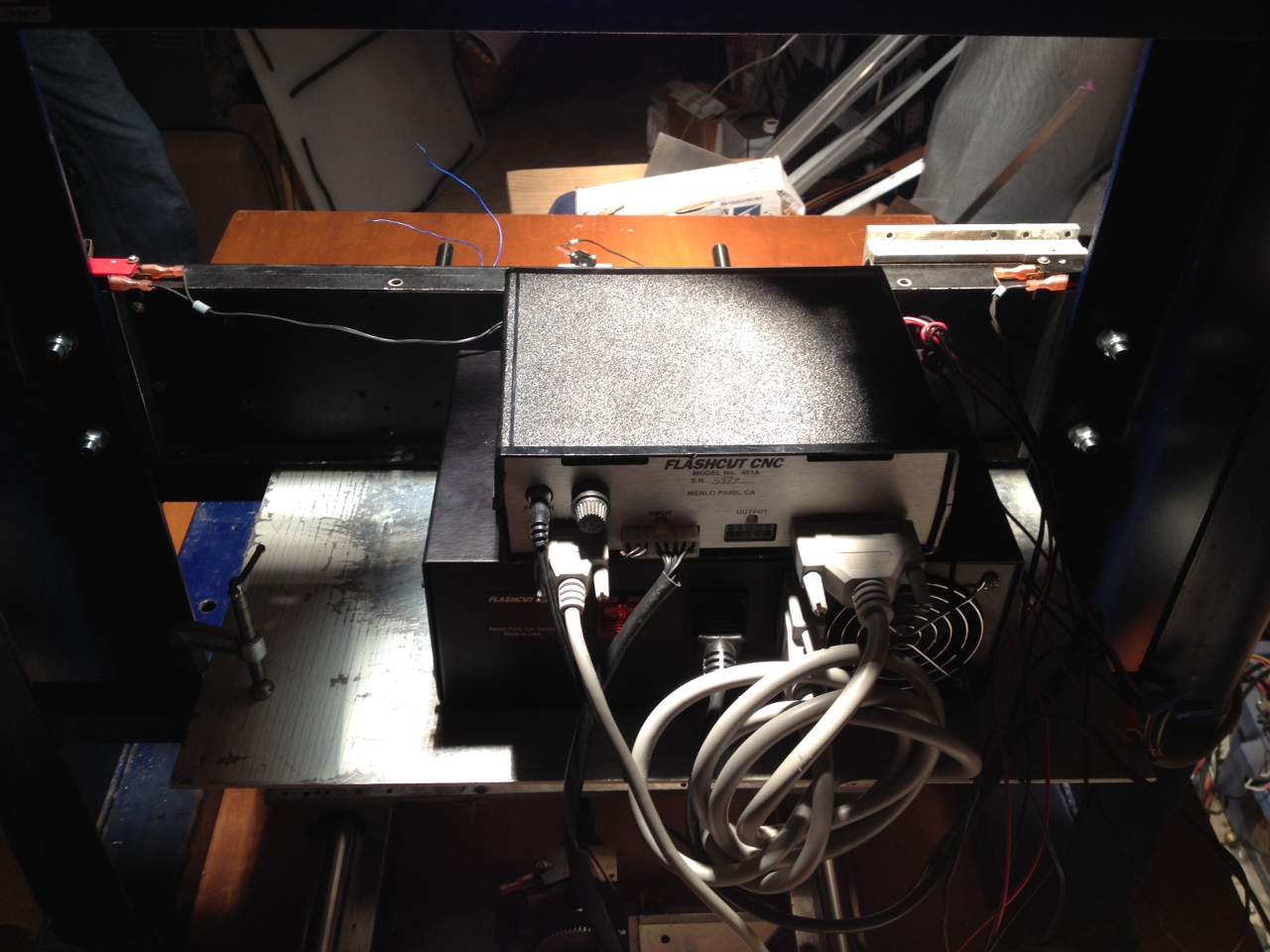
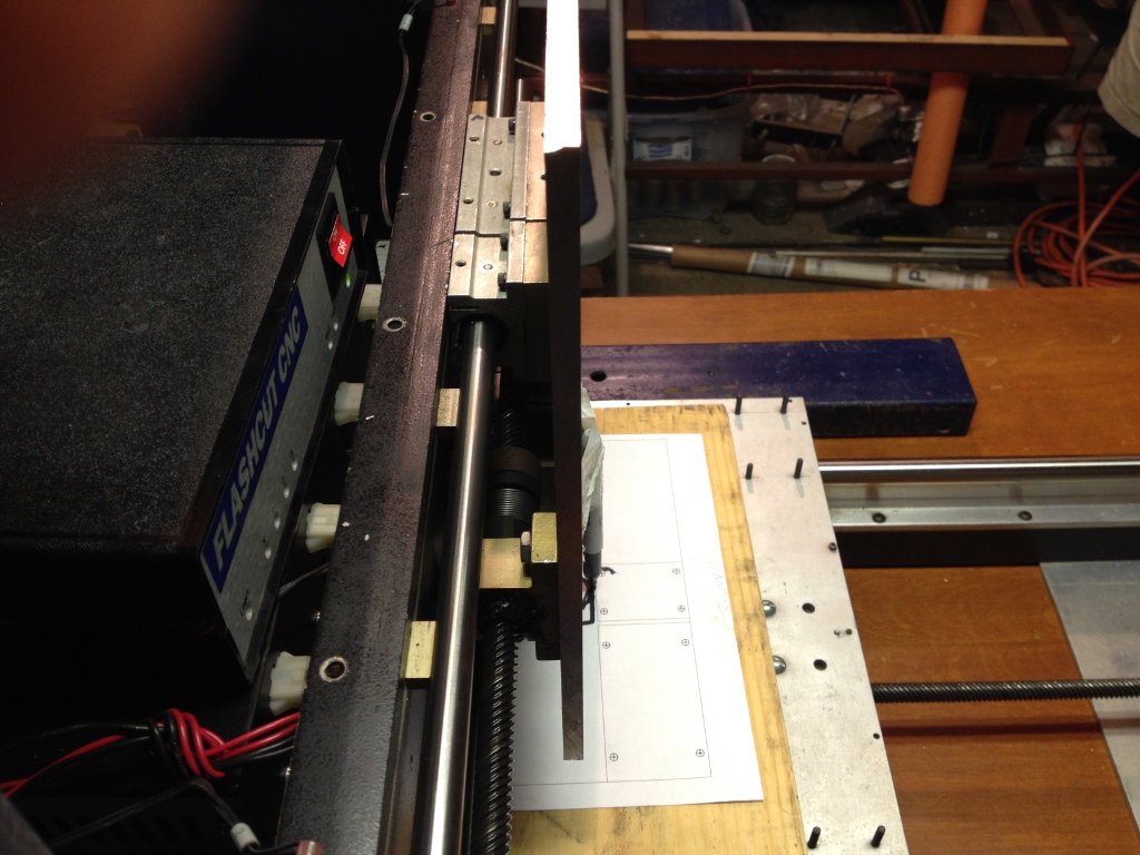
An invitation to clean out a friend of a friend's storage space yielded a FlashCut CNC stepper control system, comprising a Model 401A Signal Generator; a Model 4020 Stepper Drive Box; and FlashCut CNC 1.4 software on three 3.5" floppy disks. The controller was tested with one of the motors, with current set to 1.6A. The IB462 drivers in the FlashCut box are wired for half-stepping, giving the Rabbot X/Y axes positional accuracy of 0.0005". This discovery kicked the Rabbot project into high gear.
 The Frame
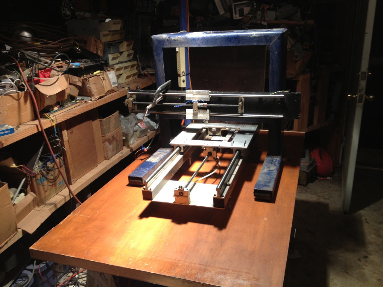
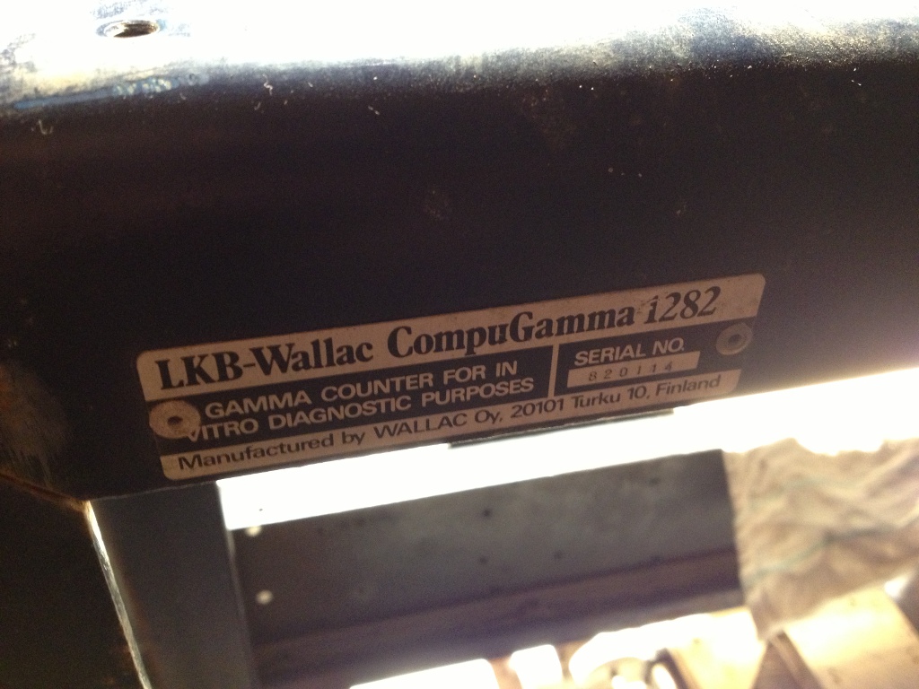
It was decided that a fixed-gantry machine would yield maximal rigidity for minimal effort. An ideal gantry frame was discovered within a LKB-Wallac CompuGamma 1282, rotting in a friend's back yard. The frame is made from 1/4" welded steel channel, designed to support a cast lead shield for a radiation detector.

 Detailed pictures of a CompuGamma 1282 in somewhat better condition.
Note the painted yellow lead shield.
Mounting the X axis
Detailed pictures of a CompuGamma 1282 in somewhat better condition.
Note the painted yellow lead shield.
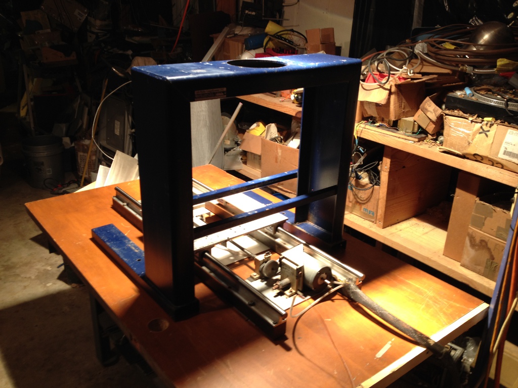
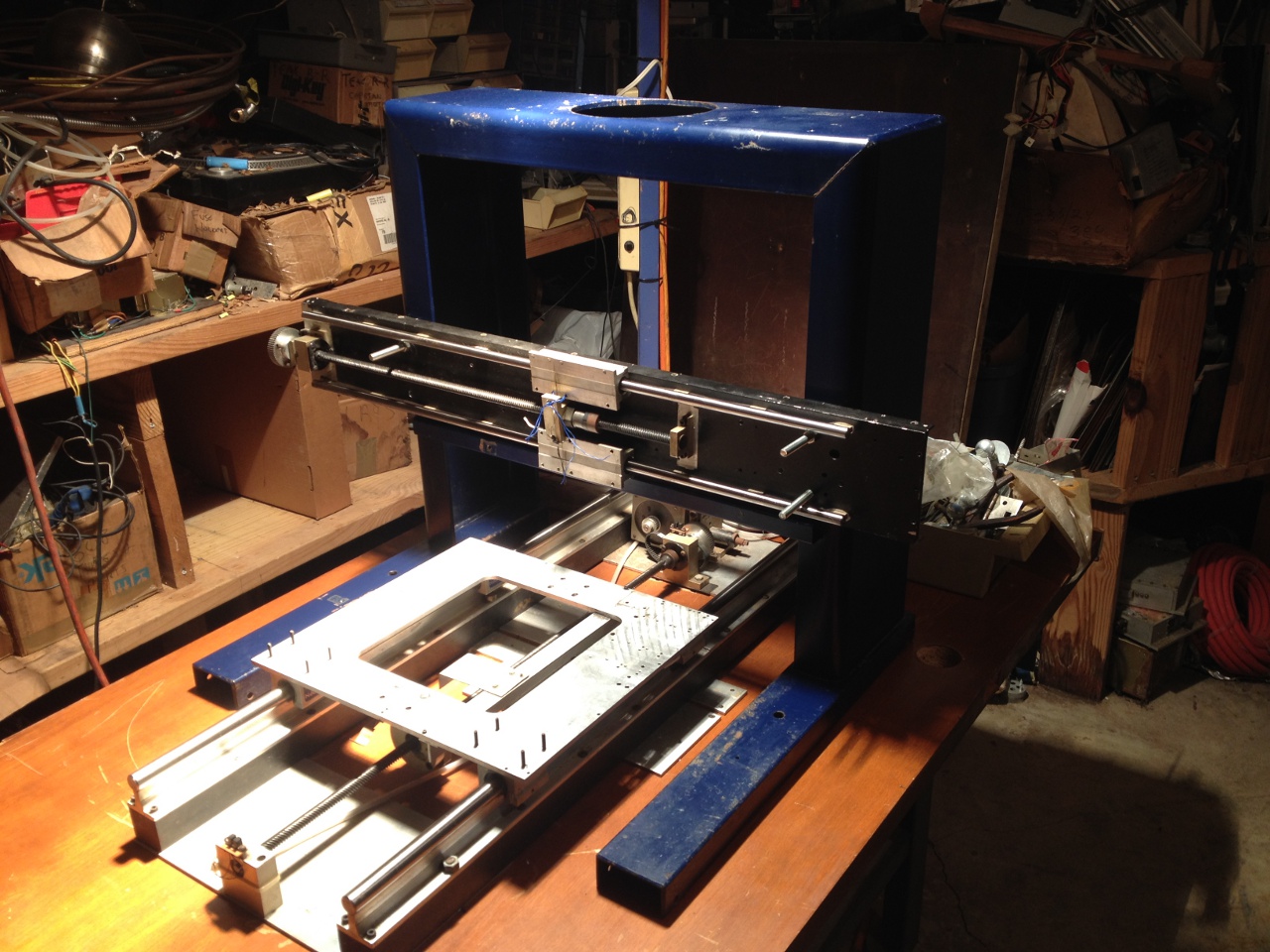
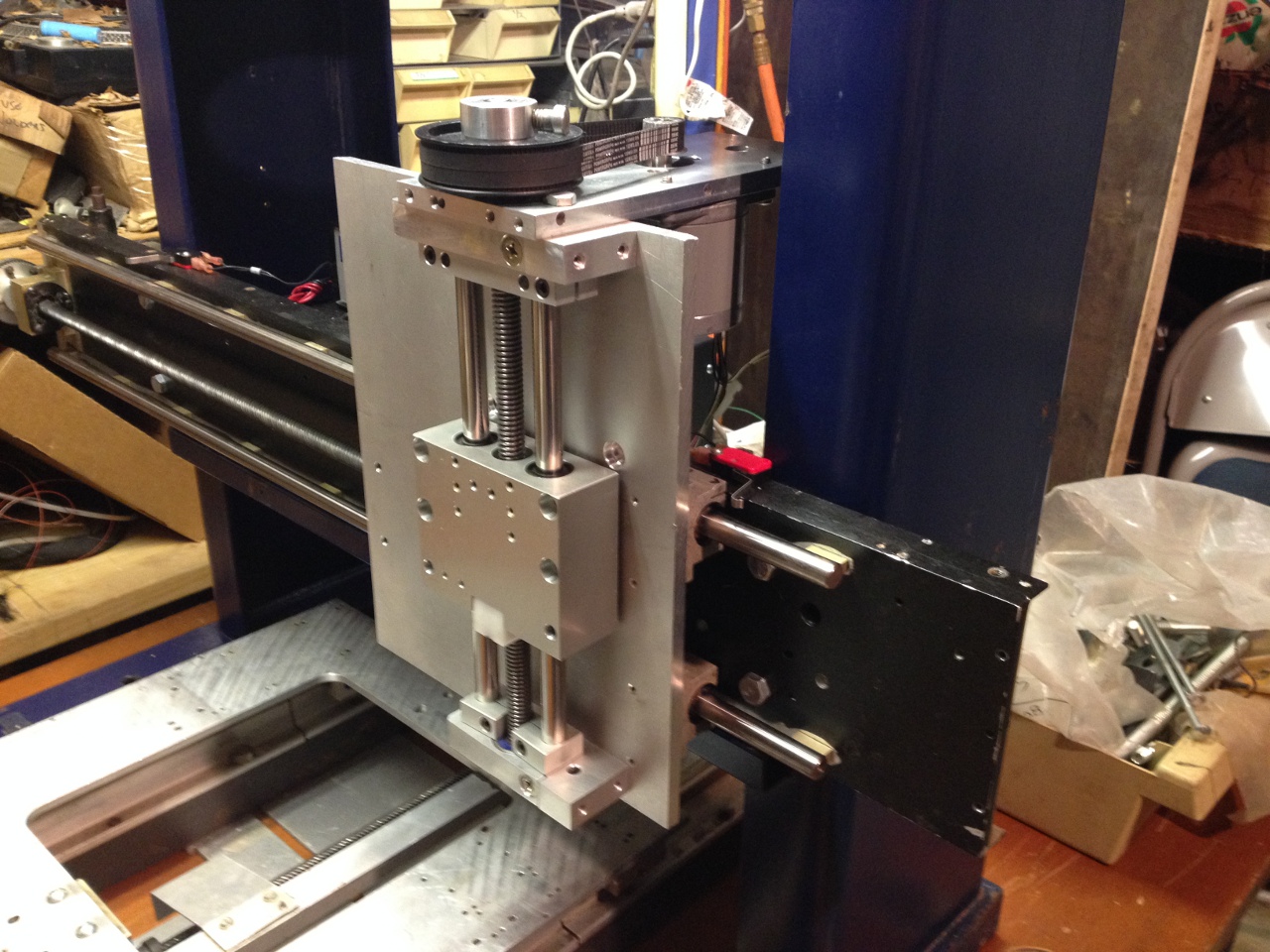
Mounting the X axisX axis assembly and gantry were bolted through a scavenged institutional door into the original steel table. The door, thought to be hardwood, was discovered to be composed of wood chips. Since the steel frame conveniently ran directly under both the X table and the gantry, these were bolted straight through the door into the frame. It is hoped that the door will dampen vibration while still providing adequate support for the geometry of the machine.


 Mounting the Y axis
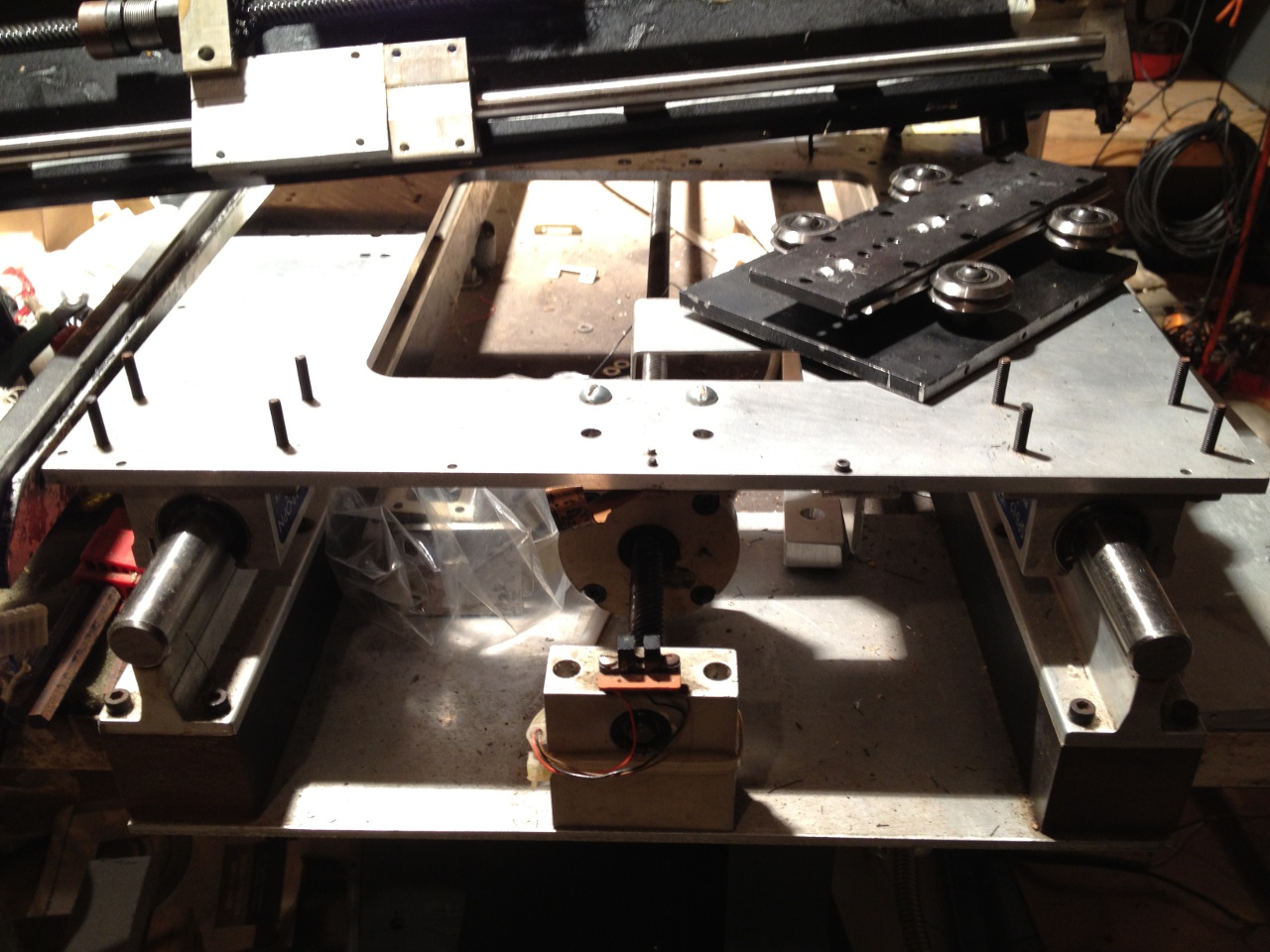
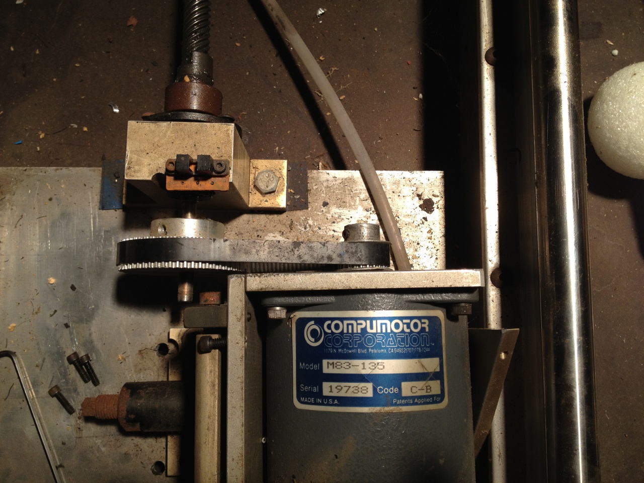
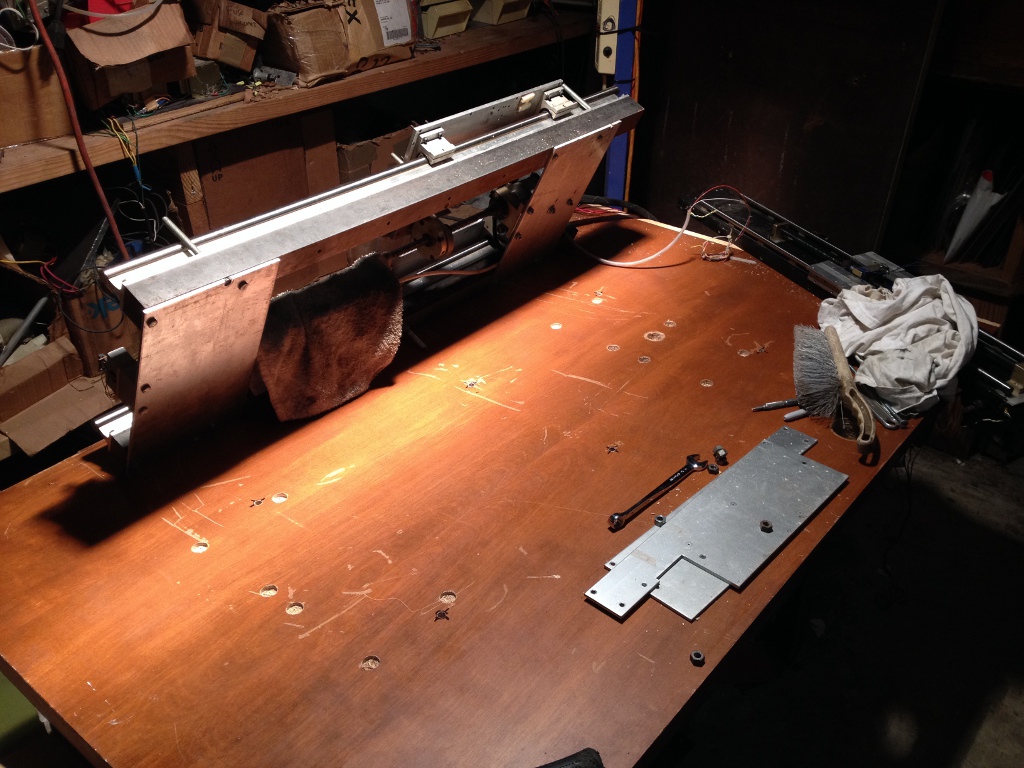
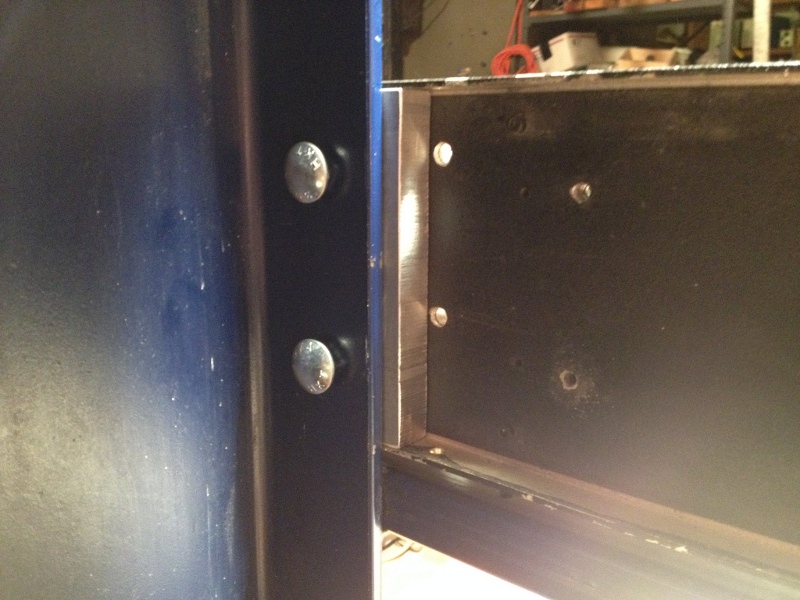
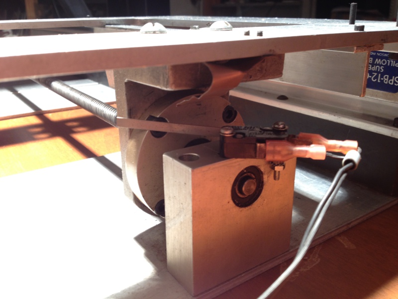
The Y axis slide assembly was bolted across the gantry, and more-or-less leveled. The most stable location for mounting bolts unfortunately interferes with the pillow blocks, limiting the usable slide area. The pictures below show temporary fasteners.
 Limit Switches
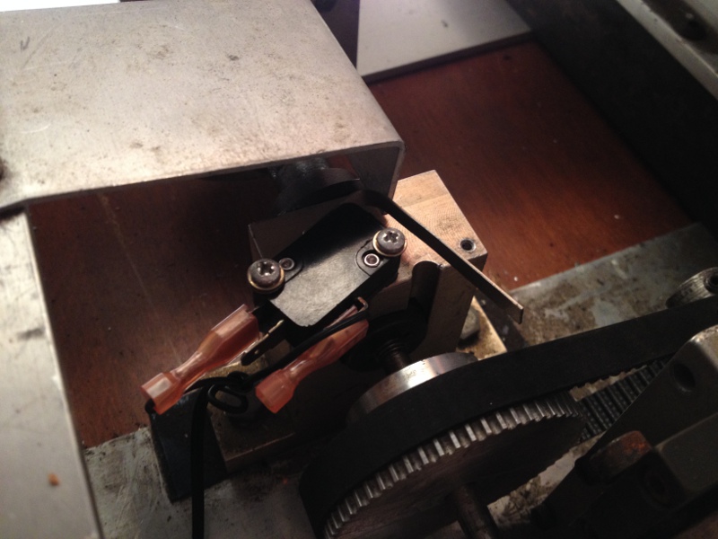
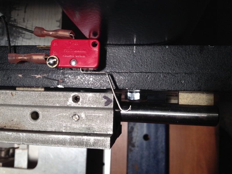
Mechanical limit switches were installed a short distance before the absolute travel limits. The FlashCut CNC controller has eight switch inputs, which can be bound to specific limit functions in software. The switches are connected Normally Closed, so wiring fault also trips the input. Absolute travel limit of the X axis is 26". With limit switches installed, it's limited to 24.625".

 Y axis carriage
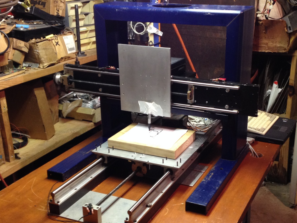
The Y axis lead nut holder and pillow blocks were measured, and a design for the carriage plate was laid out in Inkscape. A 1:1 printout was used as a template to mark an aluminum plate with a center-punch; the plate was then drilled and tapped. Time for a first light test with a permanent marker: two sample G-code programs which came with the FlashCut software. Looks encouraging!

 Z axis lead screw nut
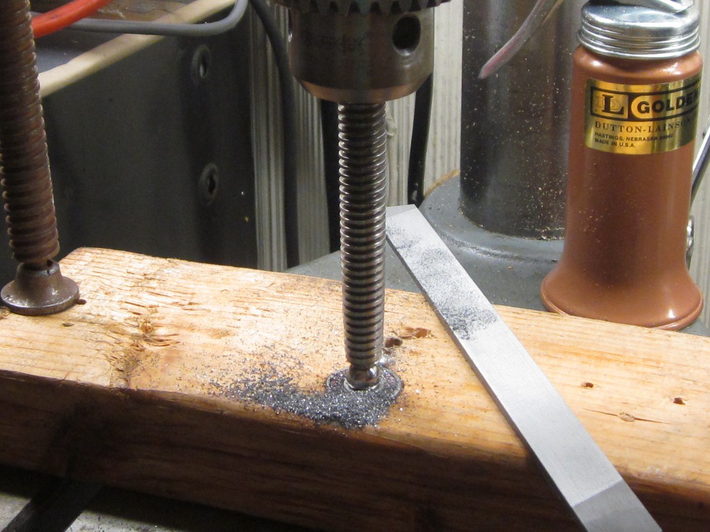
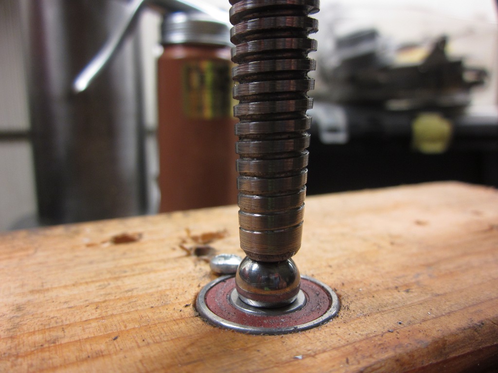
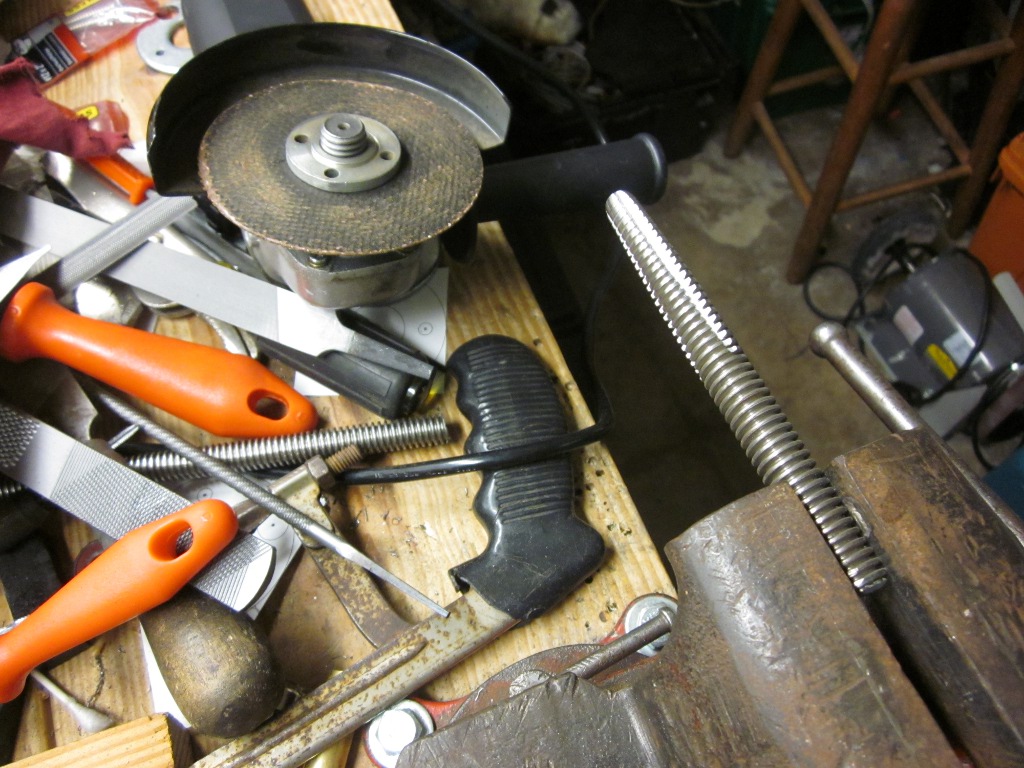
The same storage space haul which had netted the FlashCut controller, also uncovered a cache of 1/2-10 Acme threaded rod. After pricing first Acme lead nuts and then taps, a DIY tap for Delrin/acetal or UHMW plastics was made from a length of the rod. This was used to make a plastic lead screw nut for the prospective Z axis, a linear slide purchased from a thrift store. A short length of rod was chucked in the drill press. The center-drilled end was supported on a large bearing ball riding on a 608-2RS skate bearing, supported in a piece of pine drilled out as a pillow block. As the rod rotated, it was turned down with a file and lightly polished with sandpaper. The pictures below are probably worth a thousand words. An angle grinder was used to grind flutes in the tap, attempting a positive rake angle. The tap was difficult to drive through the nut material, but the resulting nut was successful enough to be incorporated into the slide.
 Another method of making acetal leadscrew nuts for very little cost.
Update 2017-04-03: The original post at the link above has been
deleted by the author. A mirror is available
here.
The remainder of the thread still contains useful information.
Z axis assembly
Another method of making acetal leadscrew nuts for very little cost.
Update 2017-04-03: The original post at the link above has been
deleted by the author. A mirror is available
here.
The remainder of the thread still contains useful information.
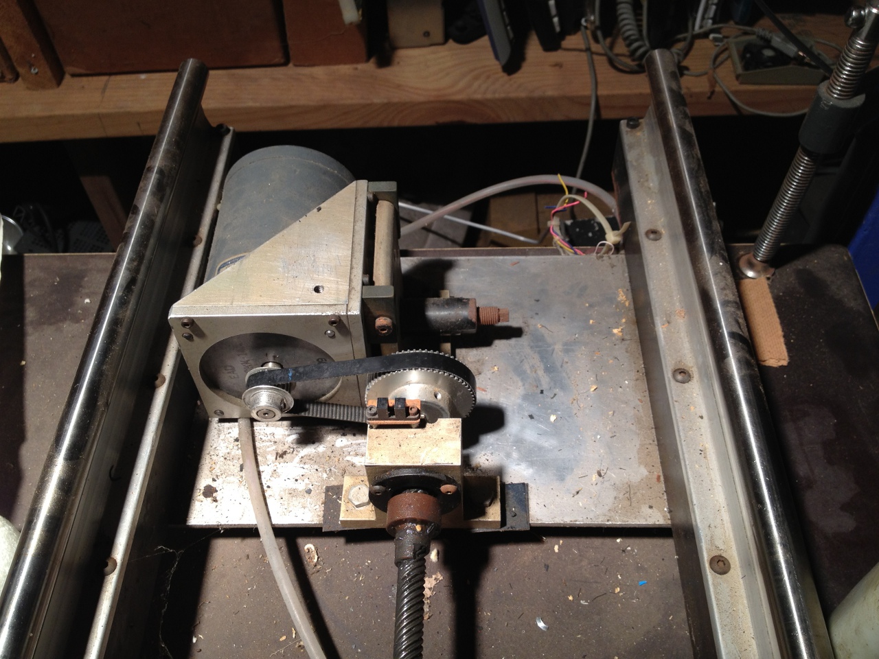
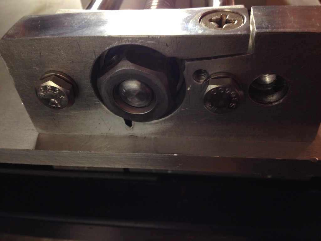
Z axis assemblyTwo pillow blocks were made from scrap aluminum, drilled with a 1-1/8" hole saw to house 1/2" ID deep-groove bearings. Clamping slits were freehanded with a hacksaw. A length of 1/2-10 Acme screw was fixed in the bearings using Acme nuts tapped and threaded for set screws, at opposing ends. (In hindsight, this wasn't a proper method of screw fixity. It relies on the rigidity of the entire assembly to counteract play, and doesn't account for thermal expansion of the screw. A better method would be to use two bearings at the motor end, and shims and opposing nuts to preload the bearings. However, no play or other problems have been observed so far. Gravitational loading of the Z axis is a mitigating factor.) A collection of MXL belts and plastic pulleys had come with the FlashCut controller; two pulleys were drilled out for 1/2" shaft diameter and screwed face to face to accomodate two of the 1/4" belts. An aluminum MXL pulley recovered from a broken DC servo motor was drilled out to 0.375" for the stepper shaft, and drilled and tapped for set screws. The motor-to-screw ratio is 3.333:1 (30 groove/100 groove). Thanks to the drive ratio and the 10-pitch screw, positional resolution is an impressive 0.00015"; unfortunately, this also results in rather slow Z axis movement. Total range of movement is 5.375", although gantry clearance is only 4.5".
| Z Axis Belts | Gates 132MXL025 | PowerGrip Timing Belt, Mini eXtra Light (MXL), 2/25" Pitch, 1/4" Width, 165 Teeth, 13.20" Pitch Length |
 Rotozip SCS01 spindle
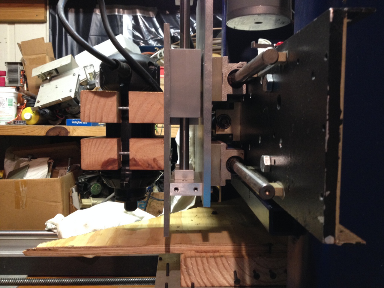
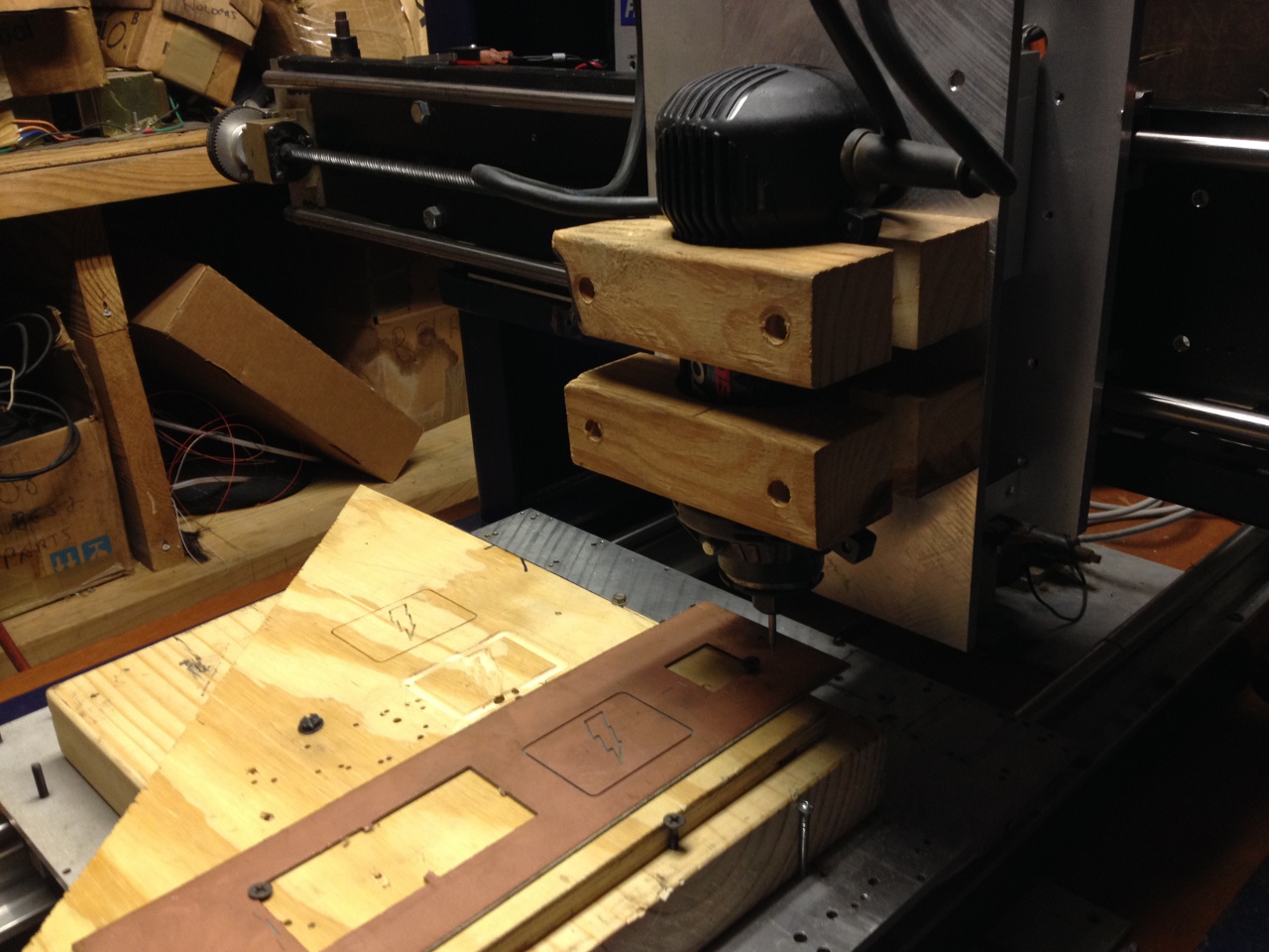
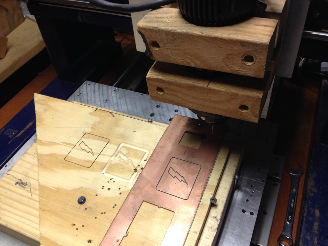
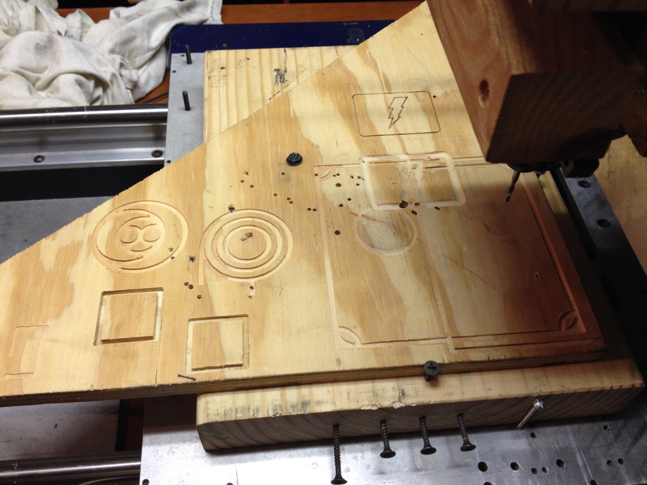
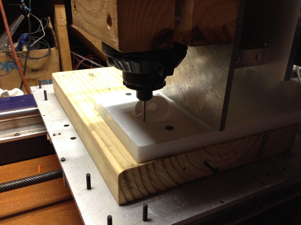
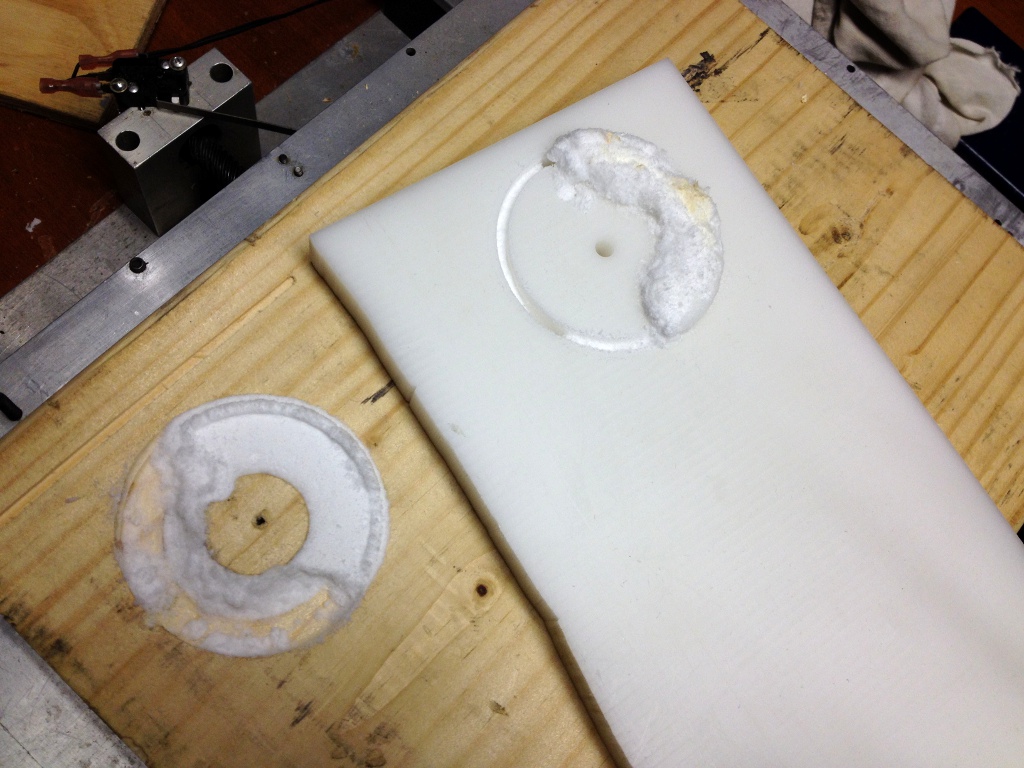
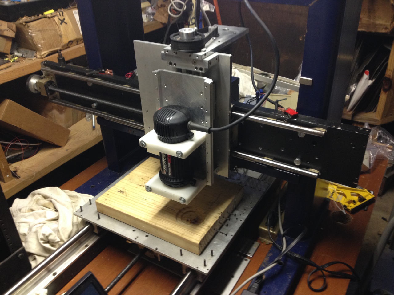
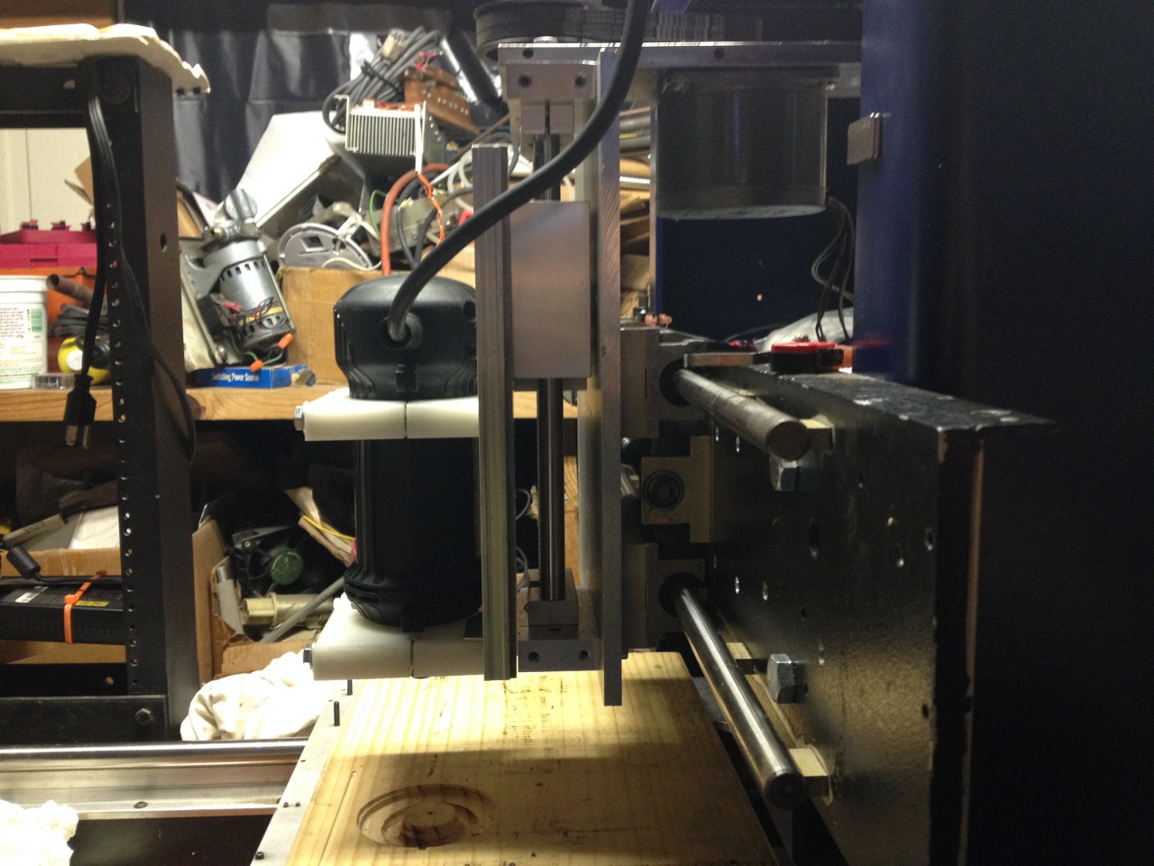
The first attempt at a spindle was a Rotozip SCS01 Type 2 spiral saw. The Rotozip uses a collet system which accomodates 1/8", 5/32", and 1/4" shank tooling; it is rated for 120VAC/4.0A, and rotates at 30,000 RPM. In the absence of suitable tools to cut a fixture matching the exact diameter of the spindle body, two chunks of 2x6 lumber were cut with a 2-1/2" hole saw to make a makeshift clamp. The constraints of this temporary arrangement severely limited the vertical travel, and the usable tooling. Test cuts were made in pine and copper-clad FR4, using a 1/4" ball-end mill and 1 MM 2-flute cutter. Various backlash and accuracy tests were performed by entering G-code coordinates by hand, and measuring the resulting cuts. The system performed reasonably well. Lateral movement along the X axis was observed in the Rotozip's plastic-located nose bearing; stainless steel foil was successfully used to shim the bearing.
 Rotozip mounting brackets
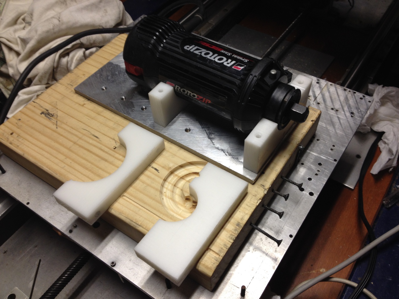
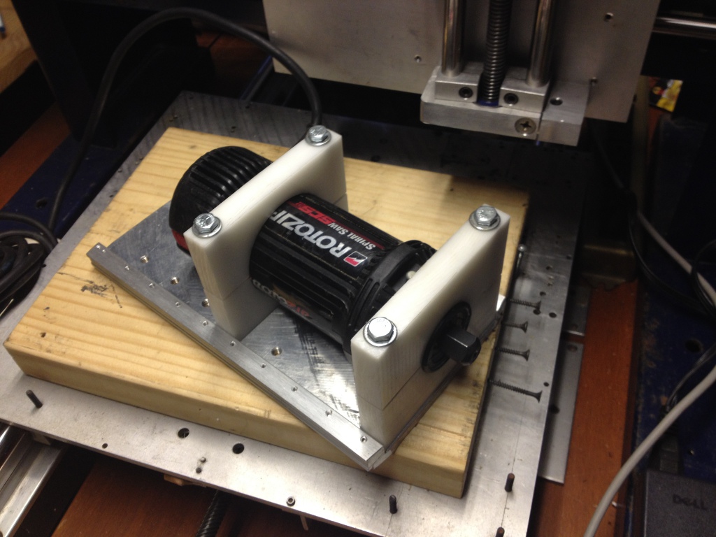
Brackets were cut from 5/8" thick acetal plastic. Toolpath calculations were performed and entered as G-code commands into the FlashCut software by hand. Owing to the awkward geometry of the wooden spindle bracket, the only tool on hand of sufficient length was a Dremel #561 HSS spiral saw bit. Since the bit cuts downward, a channel was milled in the backing board to aid in chip removal. This was only partially effective, and considerable sideways deflection of the tool was observed, but the cuts were successful.
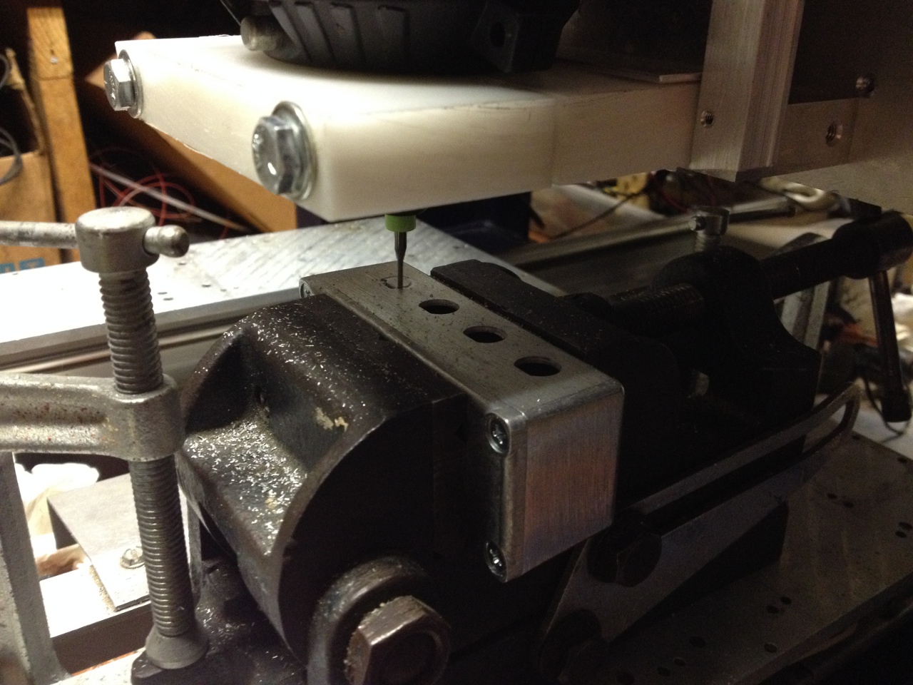
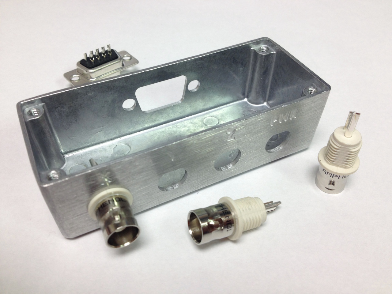
 Milling and engraving aluminum enclosures
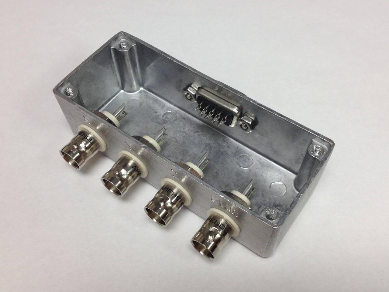
As soon as the Rabbot was basically functional, all development stopped and it was immediately pressed into service for a series of milling projects. First up was a series of diecast aluminum boxes, milled to accept BNC and DE-9 connectors:


 Milling polycarbonate spacers
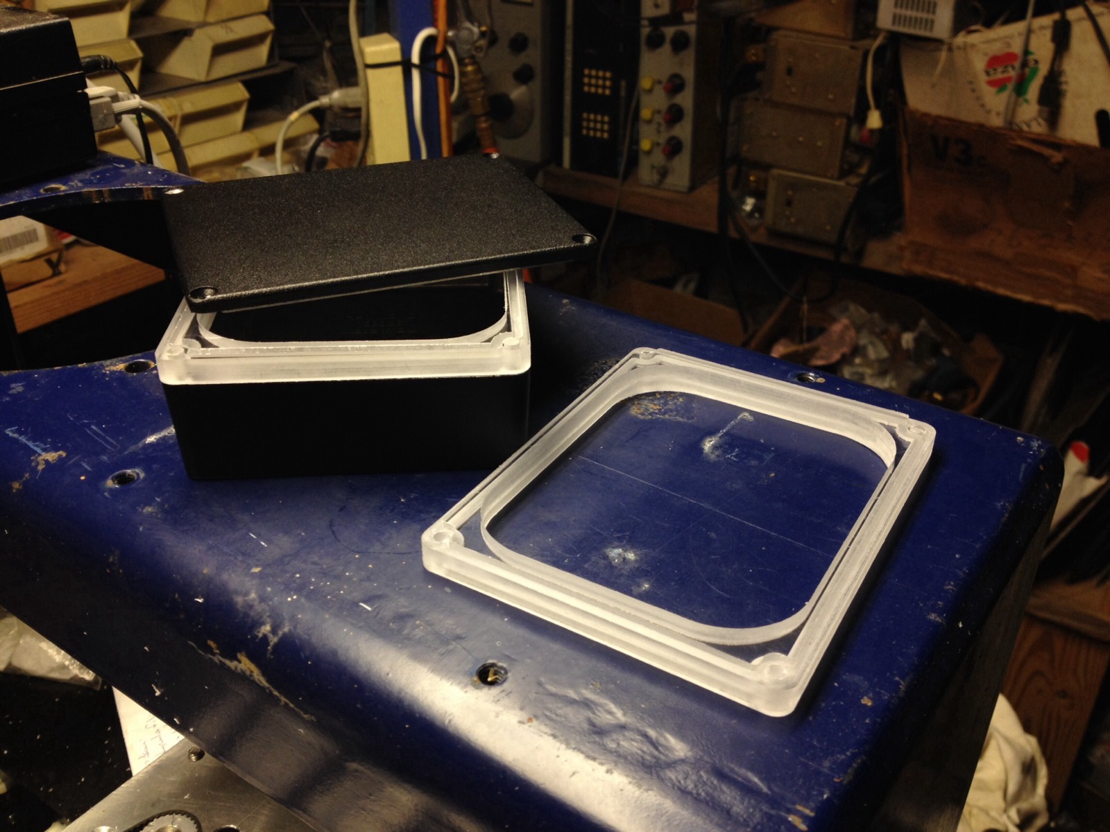
Next followed polycarbonate spacers for increasing the depth of another diecast enclosure. The paths were drawn in Inkscape, with the stroke width set to match the 1/8" tool diameter. They were then exported using the Gcodetools extension, and the resulting G-code was processed with an elaborate sed(1) script to make it more palatable to FlashCut's archaic sensibilities.

 X axis anti-backlash nut repair
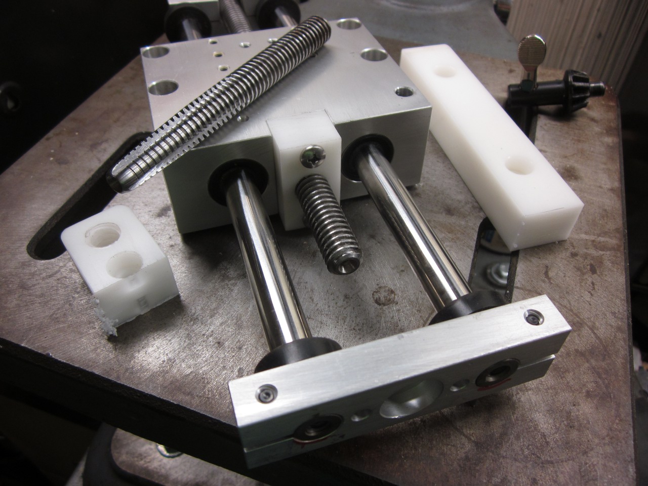
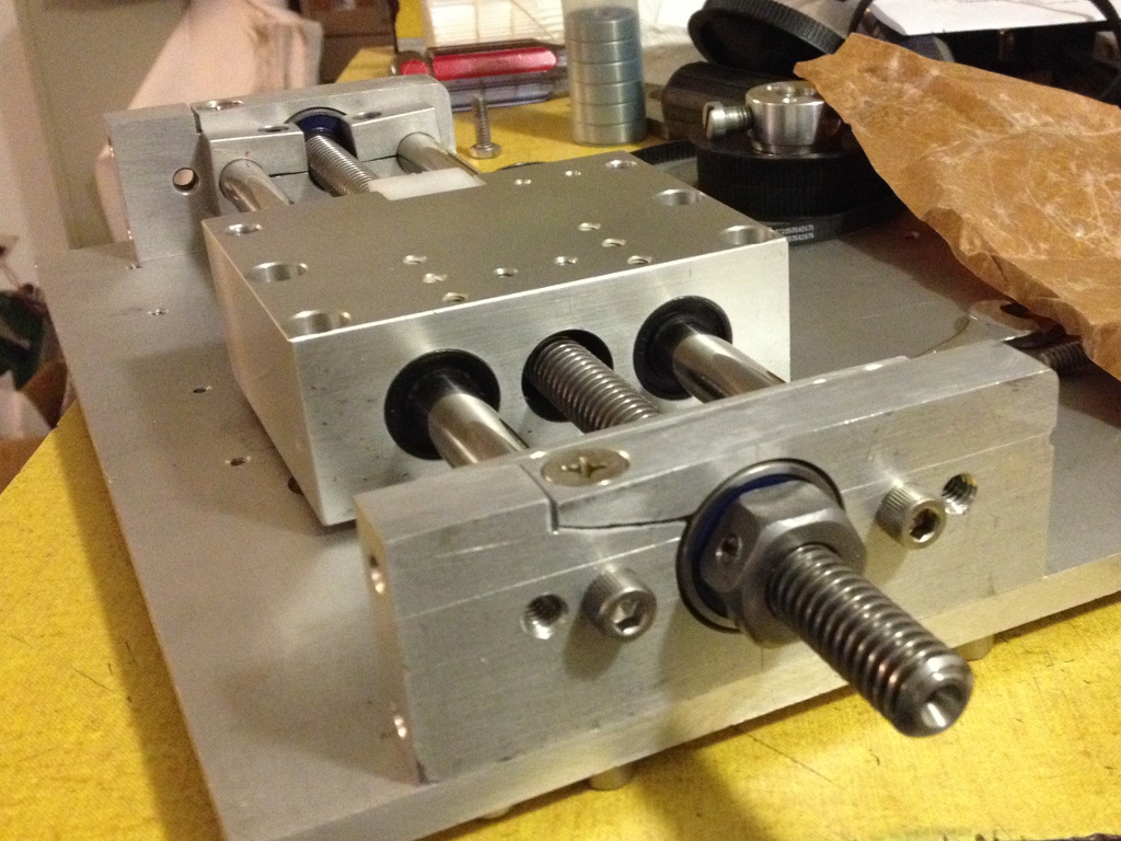
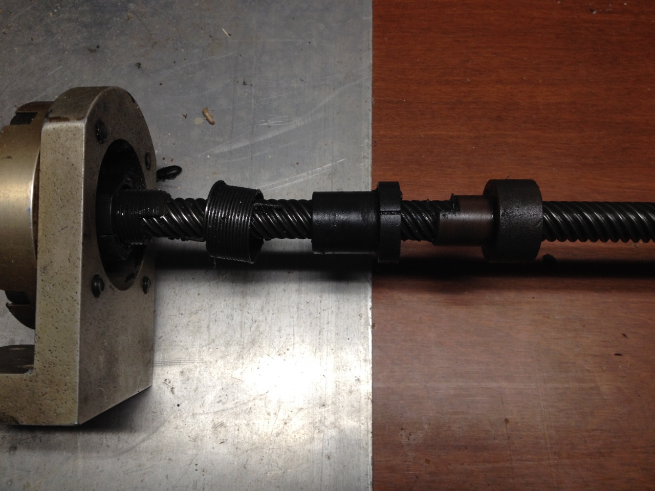
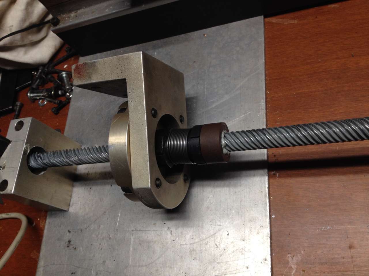
Over the course of several jobs, it became apparent that the X axis had visible backlash of about 0.015". Quick observation pinpointed the culprit. The X and Y axis leadnuts are each composed of two halves, sectioned to nest together with a loose fit inside a spring-loaded threaded collar which is adjusted to preload the free half-nut. This assembly had come completely apart on the X axis, and the free half-nut was parked at one end of the screw. Detailed analysis of photographic records of the original pile of parts reveailed that the nut had never been assembled, and somehow this was missed throughout the Rabbot project! The X axis screw and nut were removed, completely disassembled and cleaned, and reassembled to match the Y axis; which then received the same treatment. The original lubricant, which looked and smelled like black automotive grease, was removed as far as possible and renewed with white lithium grease.

 With that issue corrected, the Rabbot exhibits no visible backlash. No attempt
has so far been made, to quantify such backlash as surely still exists.
Brushless DC motor spindle
With that issue corrected, the Rabbot exhibits no visible backlash. No attempt
has so far been made, to quantify such backlash as surely still exists.
Brushless DC motor spindleAlthough the Rotozip was cheap and powerful, at 30,000 RPM with no speed regulation it was unsuitable for machining most metals aside from diecast aluminum. It also had visible runout. After considering several options, I settled on a design for a DIY belt-driven spindle using deep-groove skateboard bearings and a cheap hobby BLDC motor and ESC. This project is detailed in its own writeup, available here: DIY Milling Spindle
 Contact: reboots at g-cipher.net
XHTML and CSS compliant
:wq